background image

 Kval Return and Warranty Policy

1-15

KVAL 700-DC Operation/Service Manual

Kval Return and Warranty Policy

Kval's

 goal is to provide customers with high quality products.  If, for any reason, you are not 

completely satisfied with your purchase, please contact us at:

Email:


[email protected]

Phone: 

+1 (800) 553-5825

Restocking Fee: 

Returned manufactured products are subject to a 15% restocking

fee and applied when 

Kval

 incurs additional costs due to customer ordering error, or

manufactured parts ordered for a service related issue and subsequently returned.

Shipping Fees:


The customer is responsible for charges required to ship return items

back to 

Kval

.

Mark the Item: 

With a marking pen, clearly write on the outside of the carton RMA #

_______________

Send the Item

Return the item to this address:

Kval Inc.
RMA# ______: Kval Parts
825 Petaluma Blvd South
Petaluma, CA 94952
USA

Acceptance of Return

We can only accept items for a return if they are still in their original packaging and in undam

-

aged, resalable condition.
Returns are accepted within 45 days of purchase and with an RMA number issued by Kval Inc. 

Returns after 45 days of purchase or without a Kval Inc. issued RMA number will not be 

accepted.

Refund Turnaround Time

Refunds usually take from 3 to 10 business days to process.  The refund will be issued via the bill

-

ing method the customer used to purchase the product. 

Kval Errors

If the item must be returned because we shipped the wrong item, please call our customer service 

line immediately and arrange for re-shipment of the correct product.  Kval Customer Service will 

arrange for UPS to pick up the incorrect shipment at our expense.

Содержание 700-DC

Страница 1: ...Innovation Quality Honesty Operation and Service Manual Published April 15 2022 700 DC Frame Assembler 700 DC Operation and Service Manual ...

Страница 2: ...s a registered trademark of Microsoft Corporation All other products are trademarks or registered trademarks of their respective holders all rights reserved Reference to these products is not intended to imply affiliation with or sponsorship of Kval Incorporated Contacting Kval Customer Service For further information about this manual or other Kval Incorpo rated products contact the Customer Supp...

Страница 3: ...er experience with our product that is the manual the machinery the software etc What was easy or difficult to use or to learn If you could change something about the design what would it be Please email your comments and suggestions for improve ment to userexperience kvalinc com NOTE This is not a customer support email link For that please refer to the Customer Service contact information above ...

Страница 4: ...Kval 700 DC Operation and Service Manual ...

Страница 5: ...Lockout Tagout Power 1 10 Lockout Tagout Air Supply 1 11 Start Maintenance 1 11 Post Maintenance Steps 1 11 Zero Energy to Start Up 1 12 Getting Help from Kval 1 14 Kval Return and Warranty Policy 1 15 Send the Item 1 15 Acceptance of Return 1 15 Refund Turnaround Time 1 15 Kval Errors 1 15 Customer Errors 1 16 Shipper Errors 1 16 Warranty Replacement Parts 1 16 Safety Sign Off Sheet 1 18 A Note t...

Страница 6: ...t Up 2 16 Control Sequence Summary 2 17 Process a Door 2 17 About the Touch Screen Interface 2 20 The Main Screen 2 20 Program Screen 2 20 How to Set Staple Location 2 21 About the Maintenance Screen 2 22 Description of the Six Light Panel 2 23 Chapter 3 Maintenance Maintenance Schedule 3 2 Daily Monthly Six Month Maintenance 3 2 Lubrication Schedule 3 3 Typical Lucubration Kit 3 3 Lubrication Req...

Страница 7: ...ooting About a Typical Contactor Control 4 2 About Contactor Troubleshooting 4 3 About Limit Switches 4 4 Troubleshooting Limit Switches 4 4 Troubleshooting Electrical Problems 4 5 If the Power Stops During Normal Operation 4 5 Troubleshooting with the Status Light Panel 4 7 ...

Страница 8: ...700 DC Operation and Service Manual Table of Contents ...

Страница 9: ...description and a table of available options page 1 2 Safety First IMPORTANT safety information is described in this section page 1 5 Lockout Tagout Guidelines Procedures describing Lockout Tagout page 1 9 Zero Energy to Start Up Procedure to power up your machine for the first time page 1 12 Getting Help from Kval This section describes the method to contact the Kval Service Center for help The s...

Страница 10: ... head infeed please select Option DC Dual Controls Options Available Option Title Description Option B Auto Screw driving System for Sill Automatic screw driving assemblies with integral pilot hole drills will be mounted on each side of the sill end of the 700 DC for attaching the sill Number of screws per are controlled via a PLC preset and selector switch for jamb width Price includes automatic ...

Страница 11: ...reference points for varying protrusions are provided and can be easily adjusted manually via kip handle and slide st be adapted for out swing sills as well Option SG Staple Guns Provides the customer with the four 4 required staple guns and corresponding remote fires necessary for the 700 DC 700 DP or 700 DX to operate If cus tomer wishes to purchase and ship staple guns to Kval facility instead ...

Страница 12: ...ludes the following Operation and Service Manual includes the following Chap ter Title Description 1 Introduction Descriptions of Machine Line and Safety Information 2 Operation Interface Descriptions of how to power and operate the machine Tour of the machine 3 Maintenance Maintenance steps for the machine 4 Troubleshooting Troubleshooting tips and theory of operation ...

Страница 13: ...amaged or illegible There are three types of warning labels or decals DANGER means if the danger is not avoided it will cause death or serious injury WARNING means if the warning is not heeded it can cause death or serious injury CAUTION means if the precaution is not taken it may cause minor or moderate injury Safety Guidelines In addition to the caution and warning labels affixed to this machine...

Страница 14: ... down Never perform any maintenance unless machine is at zero state Never clean the machine while it is running Never walk away from the machine while it is running When the Machine is ON The compressed air system connected to this machine should have a three way air valve for shut off and pressure relief All cylinders on machine are under high pressure and can be very dangerous when activated Bef...

Страница 15: ...located at different locations Before performing any repairs or mainte nance lockout and tagout must be installed at all locations All maintenance and repairs to electrical circuitry should only be per formed by a qualified electrician Still has power in OFF position Electrical Prior to performing any maintenance repairs cleaning or when clearing jammed debris you must disconnect tag out or lock o...

Страница 16: ...ident If you believe any part or operation of this machine is in violation of any health or safety regulation STOP pro duction It is your responsibility to immediately protect your employees against any such hazard Additional detailed safety guidelines are included in the operating instructions of this manual Kval will be pleased to review with you any questions you may have regarding the safe ope...

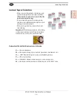
Страница 17: ...ock and tag on each disconnect Only each operator may remove their own lock and tag Important When many people are all working on the same machine you will need a multiple lockout device such as the one shown here Follow the P R O P E R lockout rule of thumb P Process shutdown R Recognize energy type electrical pneumatic mechanical etc O OFF Shut off all power sources and isolating devices P Place...

Страница 18: ...es air supply and pressure spring tension weight shifts etc 2 Inform all affected personnel of the eminent shutdown and the duration of the shutdown 3 Obtain locks keys and tags from your employer s lockout center 4 Turn off machine See Chapter 2 for power down and power up procedures 5 Turn the disconnect switches on ALL electrical and frequency panels to the OFF position Then push the red tab to...

Страница 19: ...etc are completely removed and that all guards and safety devices are installed 10 Before removing the locks and tags the person who attached them shall inspect the equipment to ensure that the machine will not be put in an unsafe condition when re energized 11 The lock and tag can now be removed only by the person s who placed them and the machine can be re energized 12 The tags must be destroyed...

Страница 20: ...ally when energy is restored Remove Locks Each operator must remove his or her own lock and tag This will ensure that all oper ators are in a safe place when the equipment is started Perform Visual Checks If the equipment is too large to see all around it station personnel around the area and sound the personnel alarm before starting the equipment If your operation is more complex your company s c...

Страница 21: ... the key to your lock Proper lockout tagout can save lives limbs and money Help make your work environment safe for you and your fellow workers Be sure to follow the P R O P E R lockout tagout procedures and that those around you do also Close the Cage Gate Verify all cage gates are securely closed Ensure all safety protocols are in effect ...

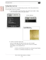
Страница 22: ...d record the serial number 3 phase volts electrical print number and air print number 2 Contact our customer support team In the U S and Canada call 800 553 5825 or fax 707 762 0485 Outside the U S and Canada call 707 762 7367 or fax 707 762 0485 Email address is service Kvalinc com Hours 6 00 AM to 4 00 PM Pacific Standard Time Monday through Thursday 6 30 AM to 1 30 PM Pacific Standard Time Frid...

Страница 23: ...rton RMA _______________ Send the Item Return the item to this address Kval Inc RMA ______ Kval Parts 825 Petaluma Blvd South Petaluma CA 94952 USA Acceptance of Return We can only accept items for a return if they are still in their original packaging and in undam aged resalable condition Returns are accepted within 45 days of purchase and with an RMA number issued by Kval Inc Returns after 45 da...

Страница 24: ...ut no more than one 1 year after delivery will the product be covered under Warranty The repair replacement or payment in the manner described above shall be the exclusive remedy of Buyer for breach of Kval s warranty or for claims based upon failure of or defect in the products regardless of when the failure or defect arises and whether a claim however described is based upon contract warranty in...

Страница 25: ...Kval Return and Warranty Policy 1 17 KVAL 700 DC Operation Service Manual Page Intentionally Left Blank ...

Страница 26: ... follow my company s safety procedures I have read and understand these guidelines Machine Safety Concerns I have been given a tour of the machine and understand all the safety labels E Stops and the actions to take in case of an emergency I will make sure all guards are in place before operation I will turn off the compressed air before loading hardware staples screws etc I will turn off the elec...

Страница 27: ... of the machine Chapter 2 at a Glance Section Name Summary Page Operator s Tour Descriptions of the operation of the parts and assemblies of the machine page 2 2 Mechanical Set Up Description of setting up the 700 DC for work page 2 6 Power Operations Description powering procedures of the machine page 2 14 Quick Start Running the machine page 2 16 Touch Screen Interface Setting up the stapling ro...

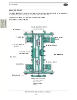
Страница 28: ...e of the door frame This section identifies the assemblies located on the 700 DC Assemblies on the 700 DC Main Control Panel Movable Fence Sill Operation Controls Hands Free buttons RH or LH Door Reverse Forward FIRE Touch Screen and Electrical Panel Fixed Fence Movable RH Gun Fixed LH Gun Movable LH Gun Fixed RH Gun Header Operation Controls Hands Free buttons Width Adjust Width Adjust Jamb Heigh...

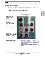
Страница 29: ...ge 2 21 for staple program ming instructions Note If Staple Sequence 0 is selected no staples will be fired Fixed Head Gun Control Enables or Disables the staple guns on the Fixed Head Movable Head Gun Control Enables or Disables the staple guns on the Movable Head Control Circuit Power up or power down the machine Fixed Side Gun Control Enables or Disables the staple guns on the Fixed Head Start ...

Страница 30: ... 16 Left Hands Free Button Press both Left Hand and Right Hand simultaneously to step through processing the door Reset Right Resets the machine to process a Right Hand door Fire Guns Press this button and the Right Hands Free Button to fire the staples Reset Left Resets the machine to process a Left Hand Door Right Hands Free Button Press both Right Hand and Left Hand simultaneously to step throu...

Страница 31: ... the Program Interface The touch screen program interface is located on the Electrical Box Staple Patterns are set and stored with this program The touch screen program interface is located on the Electrical Box Staple Patterns are set and stored with this program ...

Страница 32: ...r has factory positioned collars set for a single door width of the pair For example a setting of 32 would equal a double door width of 64 The reference collars are set at 18 20 22 24 26 28 30 32 34 36 Opts 42 and 48 There are two additional collars for user settable positions 18 20 22 24 26 28 30 32 34 36 48 Spares 42 Use the attached tape measure to set the width of the doors ...

Страница 33: ...el or the optional remote control panel This will retract the pickle forks freeing both movable fences for positioning Measuring Tape Pickle Fork Shown in the retracted position 2 Slide the movable fences to the desired location indicated by the measuring tape located on the main frame of the machine 3 Push down the width adjust button This will cause the pickle forks to extend capturing a collar ...

Страница 34: ... Adjustment End Clamps There are Length Clamp assemblies on the LH Fixed and the LH Movable Heads at each end of the machine Adjust both clamps To adjust the end clamps for 6 8 7 0 or 8 0 doors pull the pins and move clamps to the appro priate length Secure pin in the adjustment hole See the figure below Note Option D1 adds a 6 6 setting 6 8 Setting 7 0 Setting 8 0 Setting ...

Страница 35: ...E 2 Height Adjust The reference width values are 4 9 16 5 1 4 6 9 16 and 7 1 4 Note The references will work for simi lar sizes For example a 5 0 can be used in the 5 1 4 position or a 4 5 8 at the 4 9 16 position Note Staple patterns may need to be adjusted if using a non reference width jamb Adjust Head Height To adjust to different jamb widths pull the knob to the right to unlock move the clamp...

Страница 36: ...d of the machine Note The receiving conveyor or tables must be adapted for out swing sills FIGURE 3 Outswing Assembly Locations FIGURE 4 Part Descriptions for the Sill Shelf Adjusting Assembly Outswing Assembly Locations Located at the Sill end of the machine on the Movable Fence and Fixed Fence Sill Shelf The sill rests on this popup shelf Shelf Popup Cylinder Lock Unlock Bolt Outswing Bolt Setti...

Страница 37: ...both the fixed and movable fence sides 1 Determine if the incoming door is an outswing door or inswing door 2 With no air applied to the Shelf Popup Cylinder loosen the unlock lock bolt 3 Grasp the Adjustment Rail Handle and move it until the desired bolt aligns with the reference bolt on the lower brass block See settings at the next 2 steps 4 If setting to an outswing door align Outswing Bolt to...

Страница 38: ...ocking bolt 7 After securing sill assemble on the Proceed with processing the door See How to Process a Door on page 2 16 Sill Assembly Results Figure 5 shows examples of the inswing and outswing adjustments Note the height of each Sill Shelf FIGURE 5 Sill Adjustments Inswing Sill Adjustment Tighten the bolt to secure the assem bly Inswing Sill Adjustment Outswing Sill Adjustment ...

Страница 39: ... of the machine the first hole is the inswing settings and the second hole is the outswing setting of each pair See FIGURE 6 Length Adjustment Locations Option S To adjust the door length assembly pull up the spring loaded pin on the both the movable and the fixed side and move it to the appropriate length Secure pin in the adjustment hole See the figure below Header Side Length Adjust Header Side...

Страница 40: ...Starting the Control Circuit Verify Area is safe power and air are applied E Stops are out and Fence Gates are closed 1 At the Electrical Box turn the Electrical Disconnect to the ON posi tion 2 Turn the Control Circuit Switch to the ON position Approximately 3 minute boot up 3 Push the Start button All the 6 lights should be illuminated See reverse side for Tower Light Description 4 All lights on...

Страница 41: ...ering Down the 700 DC Powering down the system includes Shutting down the control power Removing power from the entire system 1 Push the Stop button 2 Turn the Control Circuit Switch to the Off position 1 At the Electrical Box turn the Electrical Disconnect to the Off position ...

Страница 42: ...ion Continue forward from the last step selected Set Up 1 Power up the 700 DC See Powering Up the 700 C on page 2 23 2 Set the Jamb Width See Width Adjust on page 2 26 3 Set the Door Length See Length Adjust Option D on page 2 28 4 If needed set Jamb Height See About the Jamb Height Adjust on page 2 9 5 If needed and option is installed set the Outswing Assembly See Option S About the Outswing Opt...

Страница 43: ...utton 2 Pull in the door verify the header is clear so the stapler heads can come in Have a little wiggle room Action Summary Choose Hand Right Hand Hands Free button Reset Right or Reset Left Bring in Side Staple Guns Sill End Both Hands Free Buttons Clamp the Head Head End Both Hands Free buttons Lower Door Sill End Both Hands Free Buttons Clamp the Door Sill End Both Hands Free Buttons Fire Sta...

Страница 44: ...r 5 Ensure the hinge jamb is in the correct position in relation to the head jamb At the Head End push both Hand Control Buttons to clamp the Header 6 Push both Sill Hand Control Buttons Drops door to lower position Push to Bring in Movable Fence Staplers Insert Jamb Insert Header Push to Clamp the Header Check Fit Push to Drop the Door to the Lower Position ...

Страница 45: ...Fire Staple Guns Simultaneously press the Fire Guns Button and the Right Hand Control Button to fire all enabled staple guns 9 Push both Hand Control Buttons Un Clamp door 10 Pull out the Door Note If changing the hand of the door repeat Step 1 Push to Clamp the Door Insert Sill Push to Fire the Staple guns Push to Un Clamp the Door ...

Страница 46: ...n on the screen to jump to that screen FIGURE 7 700 DC Main Screen Program Screen At the program screen each numbered button corresponds to a staple location on the head or the sill Each program can contain head and sill programs or head or sill separately The button label on the Main Screen will reflect the programming Select the Sill or the Head button to toggle between screens if both staple pr...

Страница 47: ...ogramming buttons are used to toggle other staple locations For example If staples where desired at 1 2 2 and 3 1 4 programming buttons 6 and 11 would be pushed 2 This location requires button 6 pressed 3 1 4 This location requires Button 11 pressed Note All programming button locations have a tolerance of 1 4 1 2 3 4 5 6 7 8 9 10 11 12 13 14 15 16 17 18 19 20 21 22 23 24 25 26 27 3 4 1 1 1 4 1 1 ...

Страница 48: ...ot lit check that area of operation Refer to the machine Electrical Prints The Back button jumps back to the Main Screen The Exit button exits the program and jumps to the Windows CE screen The Program Head Sill LEDs are the binary equivalent of the program in service See the table below TABLE 2 2 Head and Sill Programs LED 1 LED 2 LED 4 LED 8 Program OFF OFF OFF Not Used Program 0 ON OFF OFF Not ...

Страница 49: ...Operation Service Manual Description of the Six Light Panel The six lights on this panel indicate the status of the Commander III system The Sequence that the lights activate is as follows 1 Control Power 2 Overload Relay 3 E Stop 4 Stop 5 Start 6 24VDC ...

Страница 50: ...Description of the Six Light Panel KVAL 700 DC Operation Service Manual 2 24 ...

Страница 51: ...process Chapter 3 at a Glance Maintenance Schedule This section describes the assemblies to schedule for maintenance Daily Weekly 5 Six Month Checkups page 3 2 Lubrication Requirements This section describes the lubrication requirements for the machine including types of lube to use This section includes Linear Bearings Flange Bearing and Pillow Blocks Gear Motor Lubrication Requirements Ball Scre...

Страница 52: ...k Check the air filter water trap Empty if full Weekly Preventive Maintenance Op Operation Description Check Check the machine for smooth motion through a complete door cycle Clean Clean linear bearings and the chrome shaft with a clean dry cloth then lubricate Check Check all air lines electrical wiring for kinks or rubbing LUBE Refill lubricator with an ISO 32 standard hydraulic oil KVAL part SY...

Страница 53: ... Block Bearing Idler Shaft Flange Block Bearing Ball Screw Every 80 Hours of Machine Operation Tapered Bearing Once a Year Air Line Lubricator One drop of oil every 2 or 3 cycles Check the lines every week to two weeks Note Some CNC Machines drop every 5 10 cycles Either lubricant listed below is approved to use KVAL P N SYSLUBG Chevron AW Hydraulic Oil 32 G C lubricants light AW R O Mobile DTE 24...

Страница 54: ...rk fitting is basically a valve that opens under pressure to allow lubricant to pass through a channel and be forced into the voids of the bearing When the pressure stops the ball returns to its closed position The ball excludes dirt and functions as a check valve to prevent grease escaping back out of the fitting The ball is almost flush with the surface of the fitting so that it can be wiped cle...

Страница 55: ...the zerk fittings at each end of the machine and then apply EP 2 grease 3 After lubrication is completed reverse Lockout Tagout FIGURE 3 2 Fence Bearing Locations This machine is a powerful electro mechanical motion control system If servicing this machine fol low the safety guidelines Failure to do so can result in damage to equipment and or serious injury to person nel Shutdown the machine and f...

Страница 56: ...re color coded for easy identification Note The bearings are located on the bottom side of the heads some bearings may be difficult to get access to Use an extender to reach tight areas 1 Perform Lockout Tagout 2 Identify the bearings and zerk fittings on each Head and then apply EP 2 grease 3 After lubrication is completed reverse Lockout Tagout FIGURE 3 3 Stapler Bearing Locations Horizontal Bea...

Страница 57: ... information see Lubrication Schedule on page 3 3 Figure 3 4 shows the bearings located on each head assembly The bearings are color coded for easy identification 1 Perform Lockout Tagout 2 Identify the zerk fittings on the pop up shelf 3 After lubrication is completed reverse Lockout Tagout Zerk Location FIGURE 3 4 Zerk Location ...

Страница 58: ...ers delivers the lubricated air to valve banks and air cylinders FIGURE 3 5 Typical Air Line Filter and Lubrication System Adjusting the Air Line Lubricator Using the knob on the top of the lubricator adjust until one drop per every other cycle is used as observed through sight glass Shop Air Input Air On Off Muffler Filter purge Pressure Gauge with adjust Clean Dry Air CDA to Air Blow Off Lubrica...

Страница 59: ... Harmony 32 To prime the lubricator find an air line on the carriage section of the machine that is energized and disconnect it allowing the air stream to bleed air pressure away from any persons Direct the air stream at the machine so you can see when there is an oily film blowing out of the air hose Repeat this same procedure for the back section and other trouble areas It is recommended to chec...

Страница 60: ...Description of Air Input System KVAL 700 DC Operation Service Manual 3 10 ...

Страница 61: ...tor Control Describes a typical contactor control circuit page 4 2 Limit Switches Troubleshooting Limit Switches page 4 4 Troubleshooting Electrical Problems Includes voltages in the electrical panels using the Status Light panel to troubleshoot page 4 5 Refer to the Air and Electrical drawings provided with delivery of the machine The drawings are normally located in the Electrical Panel If copie...

Страница 62: ...4 7 Block Diagram of a Common Contactor Circuit High Voltage may cause personnel injury or death Troubleshooting checks must be performed by a Qualified Electrical Technician PLC Output Fuse s Line Voltage Power Contactor Control Coil Input Power Input Power Output Control Circuit Common ON Should measure Control Voltage 120 VAC here Should measure Line Voltage here Should measure Line Voltage her...

Страница 63: ...he circuit See Troubleshooting with the Status Light Panel on page 4 7 1 Open the Main Electrical Cabinet to find the Contactor Thermal Overload Assem bly 2 Press each Green Reset button on the Thermal Overload An audible click will be heard on the tripped circuit Take note of tripped circuit 3 Once the overloads are reset verify LED s are on 4 Rerun the machine and verify that motor runs without ...

Страница 64: ...ch you receive the amount of pre travel amount of movement from the arms resting position is either 5 or 20 degrees before the limit switch actuates Clicks If the arm is moved to the full extents of its travel and you do not here the limit switch Click the switch needs to be adjusted here is how you adjust it follow the following drawings The Limit Switch is activated by an assembly moving a switc...

Страница 65: ...watching the lights turn on or off Compare the lights on the IDEC or Beckhoff controllers to the electrical print to determine what systems are being affected If the Power Stops During Normal Operation 1 Check that the input power disconnect switch is not turned off 2 Check that all of the emergency stop buttons are in the normal position 3 Check the Six Lights on the Electrical Panel See Troubles...

Страница 66: ... emergency stops tripped Note Most electrical problems are related to mechanical malfunction e g stuck motors jammed chain blocked photo sensors etc Note If a solenoid valve is suspected and not cleared in the air checks section it can be electrically jumped to check operation 4 With the power off check for motor overloads by pressing each reset button usu ally at the bottom of the panel in SEQUEN...

Страница 67: ...te the cause NOTE Be sure to proceed down the table starting with the CONTROL POWER light STEP 1 Control Power Amber If light is OFF go to item A on page 4 8 STEP 2 Overload Relay Amber If light is OFF go to item B on page 4 9 STEP 3 E Stop Amber If light is OFF go to item C on page 4 9 STEP 4 Stop Amber If light is OFF go to item D on page 4 9 STEP 5 Start Amber If light is OFF go to item E on pa...

Страница 68: ...ck the wiring of the black and white wire going from the Control Transformer to the 120 VAC Terminal Strip 7 If there is no power between 1 and 2 check the secondary side of the trans former a Check between X1 and X2 If no power is measured it is a bad transformer b If there is power at X1 and X2 check the other side of the fuse If now power replace the fuse 2 Is the Disconnect Switch on the main ...

Страница 69: ...est or Stop Trip Indicator Factory Set Current Rating Adjust E Stop Light OFF Check if any E Stop buttons are pulled out NOTE Location and quantity of E Stop buttons varies depending on customer need Typical locations for E Stop buttons are near the Rear Access Gate and near the Tool Changer Access Gate Stop Light OFF Check for 120 VAC between 2 and 4 If there is voltage press the Start button If ...

Страница 70: ...heck for DC voltage where those wires were disconnected If no voltage Check the input side for 120 VAC If no 120 VAC check the fuse If there is 120 VAC and no 24VDC replace the 24VDC Power Supply If there is 24VDC Reconnect the V wire to the 24VDC power supply Trace the output wire to the DC terminal block Disconnect all 24V positive wires from the DC from the DC terminal block except the output w...

Страница 71: ......
Страница 72: ...partment Kval Incorporated 825 Petaluma Boulevard South Petaluma CA 94952 Contacting KVAL Phone and Fax In the U S and Canada call 800 553 5825 or fax 707 762 0485 Outside the U S and Canada call 707 762 7367 or fax 707 762 0485 Email service kvalinc com http www kvalinc com ...

Отзывы: