- 29 -
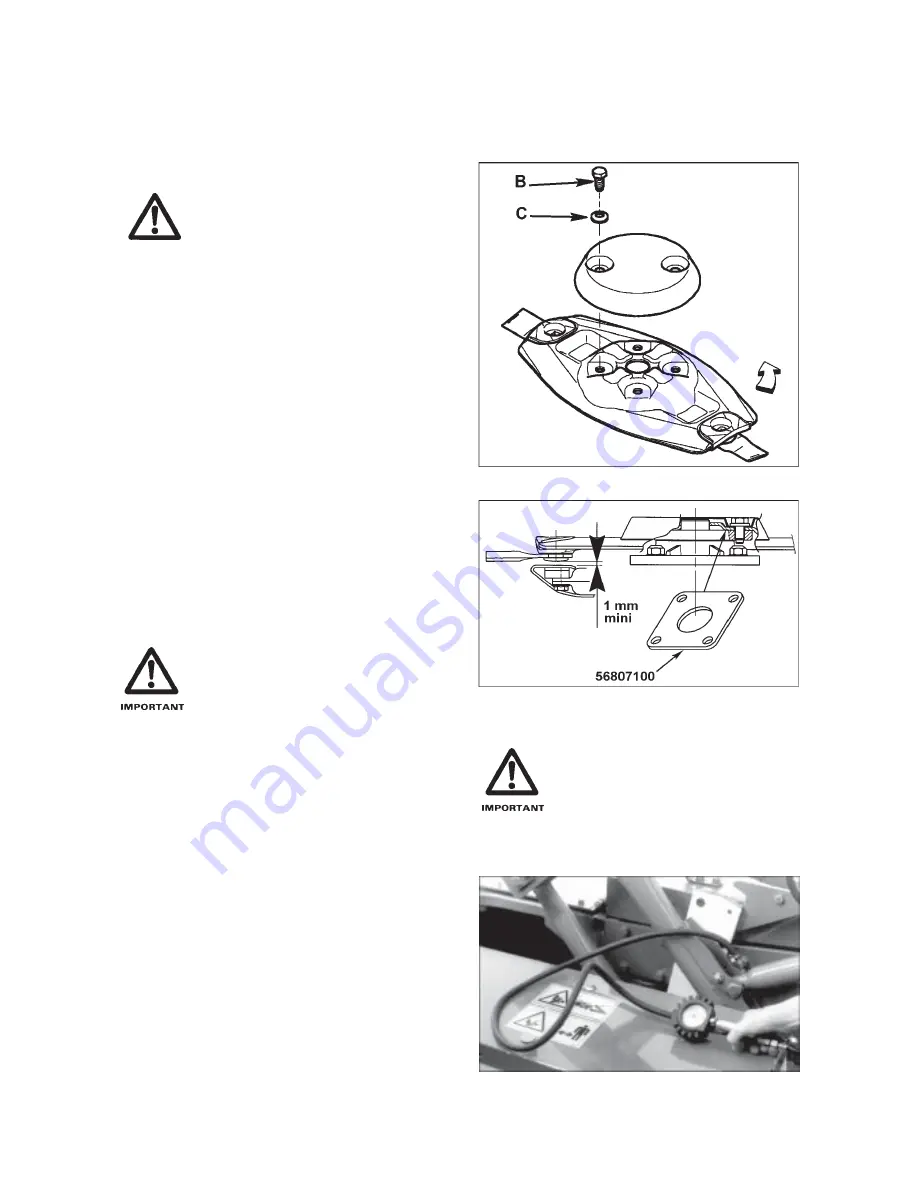
Worn knives should either be turned over on the same disc to use the other cutting edge, or replaced. When turning
or replacing the knifes, make sure there is a 1 mm minimum gap between the knives or their mounting bolts and
the cutterbar wear plates. If otherwise, insert one (maximum two) distance spacer(s) (code 568 071 00) between
the discs and the disc bearing stations (see fig. 11). Dull knives require more horse power to cut the crop and will
leave an uneven stubble.
IMPORTANT : ALWAYS REPLACE
SECURING ELEMENTS (LOCK-
NUTS AND BOLTS) WHEN THEY
HAVE BEEN REMOVED 5 TIMES.
CAUTION : ALWAYS REPLACE
D A M A G E D K N I V E S , N E V E R
STRAIGHTEN A BENT KNIFE.
NEVER REPLACE ONE KNIFE ONLY
PER DISC, ALWAYS REPLACE
BOTH OF THEM TO AVOID CREAT-
ING AN OUT-OF-BALANCE FORCE.
Discs are secured by 4 nipple screws (B) and 4 conical
spring washers (C) on a hub (fig. 10).
Two of these diametrically opposite bolts are also used
to secure the conical covers on top of the discs.
Tighten all 4 bolts to a torque of 12 daNm (90 ft.lbs).
The discs must have their largest diameters positioned
at right angles to each other (see photo 31). This
positioning must be scrupulously respected so as to
avoid interference between the knives. Take extra care
when fitting the conical spring washers (C) (fig. 10),
which must be positioned with the conical centre at the
top.
Discs supplied through our spare parts
department come with a 1 mm spacer
(part no. 568 071 00) (fig. 11) attached
to them. When installing a new disc
check if the gap between the blades
or their mounting bolts and the
cutterbar protection shields is at least
1 mm. If this is not the case fit the 1
mm spacer between the disc and its
mounting hub for increased clea-
rance (fig. 11).
LIFTING CYLINDERS
The larger cylinders’ piston end is air pressurized for a
quicker adaptation to uneven grounds (depressions)
when the tractor valve is shifted in the free floating
position.
To check the air pressure, place the machine in
working position and the tractor’s single acting hydraulic
valve in the free floating position.
The cylinder barrel must then be pressurized at 3.5
bars/50 psi when the cylinder rods are completely
extended (photo A).
REGULARLY CHECK ALL NUTS
AND BOLTS FOR CORRECT TIGHT-
NESS, PARTICULARLY THOSE
SECURING DISCS AND BLADES.
Fig. 10
Fig. 11
A


