SECTION 6
LOW PRESSURE WATER
Page 6-3
49831928
6.1
Oil Cooling Water Supply
(See Figure 6.2)
The hydraulic oil cooling water circuit includes an oil- to- water heat exchanger (1), an
automatic water modulating valve (2), and associated bulkhead fittings to connect
inlet and outlet water to source/ drain piping/ hoses as appropriate. The water
modulating valve provides accurate and reliable regulation of oil temperature in the
hydraulic reservoir (8).
Cooling water is provided by the SL-IV Waterjet Pump user, and can be either tap
water (A) or built into a chiller circuit (B) that re-circulates cooling water, reducing
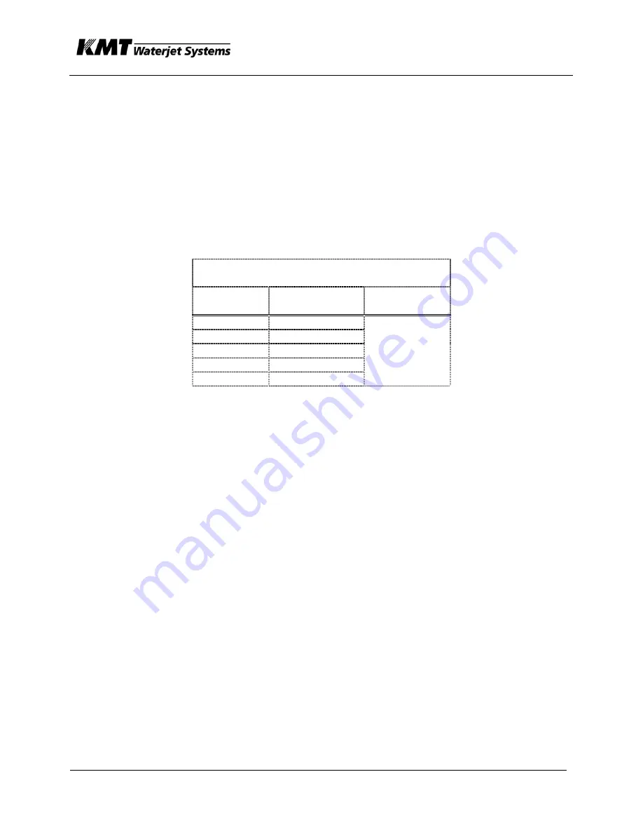
water consumption. See Table 6.3 for estimated water flow requirements. Note that
actual water flow will vary due to open/close cycling of the water modulating valve, as
well as variations in operating pressure, and pump duty cycle.
Table 6.3. Cooling Water Requirements
—SL-IV Waterjet Pumps
Hp (Kw)
Gpm (liters/
min)
At Temp.
30 (22)
50 (37)
60 (44)
75
100 (75)
4.5
70 deg F
Sometimes Waterjet customers pipe cooling water from a cooling manifold or series
circuit. Issues with low supply pressure or high supply temperature may arise in
connection with this cooling system.
To raise or lower hydraulic oil operating temperature, an adjustment on the water
modulating valve (2) increases or decreases force on a spring. Turning the screw
counterclockwise causes increased water flow while DECREASING oil temperature.
Likewise turning the screw clockwise INCREASES oil temperature. The water
modulating valve includes a sensor bulb (8) that mounts into a thermal well built into
the hydraulic reservoir.
The heat exchanger (“cooler”) (1) is a flat plate design, providing efficient transfer of
heat from hydraulic oil to cooling water in a compact, reliable package. Two each
hydraulic hoses and two each water hoses connect to the flat plate heat exchanger.
Cooling water IN connects to the port nearest hydraulic oil OUT, hence the term
”counter flow” is used to describe this arrangement. On occasion the water passages
in the heat exchanger (1) can become partially blocked by rust or solids buildup in the
water. Back flushing may correct this problem.
For a more complete discussion of the hydraulic side of the cooling circuit, refer to
Section 10.
Содержание STREAMLINE L-IV 50
Страница 55: ...SECTION 4 MAINTENANCE Page 4 9 49831902...
Страница 140: ...SECTION 12 PARTS LISTS Aug 2003 page 12 5 80081540...
Страница 142: ...SECTION 12 PARTS LISTS Aug 2003 page 12 7 80081540...
Страница 144: ...SECTION 12 PARTS LISTS Aug 2003 page 12 9 80081540...
Страница 146: ...SECTION 12 PARTS LISTS Aug 2003 page 12 11 80081540...
Страница 148: ...SECTION 12 PARTS LISTS Aug 2003 page 12 13 80081540...
Страница 150: ...SECTION 12 PARTS LISTS Aug 2003 page 12 15 80081540...
Страница 152: ...SECTION 12 PARTS LISTS Aug 2003 page 12 17 80081540...
Страница 154: ...SECTION 12 PARTS LISTS Aug 2003 page 12 19 80081540...
Страница 156: ...SECTION 12 PARTS LISTS Aug 2003 page 12 21 80081540...
Страница 158: ...SECTION 12 PARTS LISTS Aug 2003 page 12 23 80081540...
Страница 160: ...SECTION 12 PARTS LISTS Aug 2003 page 12 25 80081540...
Страница 162: ...SECTION 12 PARTS LISTS Aug 2003 page 12 27 80081540...
Страница 164: ...SECTION 12 PARTS LISTS Aug 2003 page 12 29 80081540...
Страница 166: ...SECTION 12 PARTS LISTS Aug 2003 page 12 31 80081540...
Страница 168: ...SECTION 12 PARTS LISTS Aug 2003 page 12 33 80081540...
Страница 170: ...SECTION 12 PARTS LISTS Aug 2003 page 12 35 80081540...
Страница 172: ...SECTION 12 PARTS LISTS Aug 2003 page 12 37 80081540...
Страница 173: ...Date 7 29 2003 Time 11 47 13 AM Title J cad Release 4983 49835622 DWG...
Страница 174: ......
Страница 175: ......
Страница 176: ......
Страница 177: ......
Страница 178: ......


