30
4.4
Display Messages/Troubleshooting
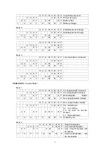
This section lists the event and alarm messages that the UPS might display. The messages
are listed in alphabetical order. This section is listed with each alarm message to help you
troubleshoot problems .
Display messages
Events:
No.
Display message
Meaning
1
Initializing
The DSP and MCU are in Initializing.
2
Standby
3
Non-Output
The UPS does not provide power to the load equipment.
4
On Bypass
Inverter output is turned off and the load connected at
the inverter output receives power from utility line via
STS.
5
On Line
Inverter output power is the primary energy source to load
6
EPO Activated
Emergency Power Off Switch has been activated.
7
Automatic Self Test
The UPS has started pre-programmed battery test.
8
Inverter in soft starting
The inverter is in soft-starting
9
System Fault Detected
The system has detected an internal error
10
MBS status
status of maintenance bypass
11
EPO status
status of EPO(emergency power off)
12
Int. Input Switch closed
The internal input breaker is closed manually.
13
Int. Input Switch opened
The internal input breaker is opened manually.
14
Rectifier Deactivated
The rectifier has been deactivated.
15
Rectifier Activated
The rectifier has been activated.
16
Rectifier Current Limit
When the input voltage is at 208V~305V, the output of
the UPS will not be interrupted, but it will be at current
limit, for example, to reduce charge current. When the
load connected exceeds its limit, the warming shall
occur.
17
Battery charge deactivated
The charger has been deactivated.
18
Positive Battery Boost
Charging
The Positive battery is in boost charge, which is
Constant voltage boost charge mode or constant current
boost charge mode.
19
Positive Battery Float
Charging
The Positive battery is in float charge.
20
Negative Battery Boost
Charging
The Negative battery is in boost charge.
21
Negative Battery Float
Charging
The Negative battery is in float charge.
22
Int. bypass Switch Opened
The internal bypass breaker is opened manually
23
Int. bypass Switch Closed
The internal bypass breaker is closed manually
24
Int. output Switch Opened
The internal output breaker is opened manually
25
Int. output Switch Closed
The internal output breaker is closed manually
26
Ext. bypass Switch Opened
The external bypass breaker(parallel system) is opened
27
Ext. bypass Switch Closed
The external bypass breaker(parallel system) is closed
28
Ext. output Switch Opened
The external output breaker(parallel system) is opened
29
Ext. output Switch Closed
The external output breaker(parallel system) is closed
30
Coming to Interval transfer
Allows transfer to bypass or inverter with 3/4 cycle
break. Use of this command will drop load.
Содержание YDC9300-RT Series
Страница 1: ......


