KSB moviBOOST VP Скачать руководство пользователя страница 7

moviBOOST VP

5

Installation at site

5.1

Readiness for operation

The owner or the owner’s representative must report the unit’s
readiness for operation to the responsible authorities (normally
either the water company or the Trade Inspection Office). Prior
to commissioning, the installation contractor must demonstrate
conclusively that the installation requirements have been
complied with.

The power supply line must be installed / connected by a duly
authorised company.

5.2

Installation and location

The moviBOOST must be located either in the technical
equipment room or in a well-ventilated, frost-free, lockable
room used for no other purpose. No harmful gases are allowed
to enter the place of installation. An adequately sized drain
connection (leading to a sewer or equivalent) must be provided.

The unit is designed for a maximum ambient temperature of
0

0

C to +40

0

C at a relative humidity of 50%.

moviBOOST units should not be installed next to sleeping or
living quarters.

Thanks to the anti-vibration mounts, the moviBOOST VP unit
is adequately insulated to prevent transmission of solid-borne
noise.

5.3

Piping

All piping must be installed without transmitting any stresses
or strains. The use of length-limited expansion joints is
advisable (see Accessories).

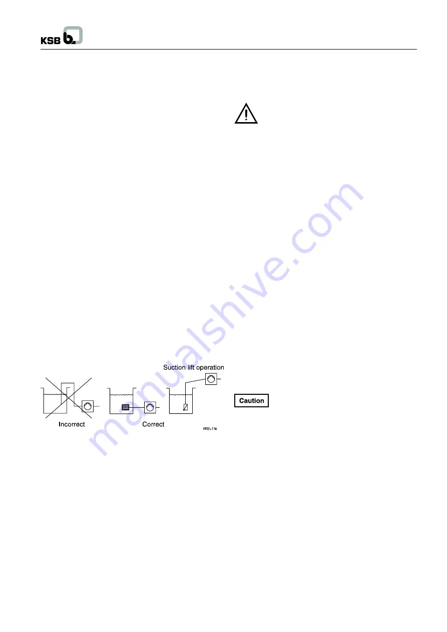
The formation of air pockets must be avoided. For suction lift
operation, the suction side piping must be laid with a
continuously rising slope.

5.4

Foundation

The package unit is designed for installation on a level
concrete floor. Its anti-vibration pads provide adequate
insulation against solid-borne noise.

5.5

Location

Prior to installing the unit, remove the packaging.

Connect the unit’s inlet and discharge pressure lines with the
corresponding distribution lines.

In order to avoid transmission of piping forces onto the system
and transmission of solid-borne noise, we recommend
installing length-limited expansion joints.

The unit must be accessible to allow maintenance and repair
work.

5.6

Installing a pressure reducer

A length of approximately 600 mm must be provided on the
inlet pressure side to accommodate a pressure reducer, if
necessary.

A pressure reducer must be installed if the inlet
pressure fluctuation is so high that the PBU must be
stopped or if the total system pressure (inlet pressure
plus shut-off head) exceeds the design pressure.

The maximum pump discharge pressure at zero flow point is
reached in manual mode.

For the pressure reducer to function properly, there must be a
minimum pressure gradient of 5 m. The pressure downstream
of the pressure reducer (downstream pressure) is the basic
parameter for defining the pump head.

Example :

The inlet pressure fluctuates between 4 and 8 bar. A pressure
reducer is needed upstream of the unit on the inlet pressure
side.

Min. inlet pressure (H

vor

) = 4 bar

Minimum pressure gradient = 0.5 bar
Downstream pressure = 3.5 bar

5.7

Location and installation of unpressurised
inlet tanks

5.7.1 Location

Inlet tanks may be installed in the same location as the
pressure boosting unit. Installation and location are governed
by the rules applicable to the pressure boosting unit (see 5.2).

5.7.2 Installation

The closed PE inlet tank (under atmospheric pressure)
available as an accessory must be installed as described in
the installation instructions supplied with the tank.

Mechanical and electrical installation of the tank must be
completed prior to commissioning of the unit.

Clean the tank before filling it.

5.8

Valves and fittings

All other valves and fittings in the service pipes, e.g. gate
valves, water meters and non-return valves must be sized in
accordance with the data provided by the responsible water
company.

5.9

Noise characteristics

moviBOOST VP units are available with different pump models
in variable numbers.

Therefore, the total sound pressure level in dB(A) needs to be
calculated.

For the noise level of the individual pumps refer to the pumps
Operating Instructions.

5

Содержание moviBOOST VP

Страница 1: ......

Страница 2: ... EMC recommendations 6 6 5 Temperature requirements 6 6 6 Humidity requirements 6 6 7 Installation altitude 6 6 8 Pollution exposure 6 6 9 Checking the voltage 6 6 10 Logic circuit diagrams 6 6 11 Over load relay 6 6 12 Potential equalization 6 Contents Sr no Description Page no 7 Commissioning start up 6 7 1 Preparations for commissioning start up 6 7 2 Test run 6 7 3 Checking the direction of ro...

Страница 3: ... for fluid connections must always be complied with and be kept in a perfectly legible condition at all times 2 2 Personnel qualification and training All personnel involved in the operating maintaining servicing inspecting and installing the unit must be fully qualified to carry out the work involved Areas of responsibility and personnel monitoring must be clearly specified by the operator If the...

Страница 4: ...gulations must be complied with Furthermore local conditions must be taken into account for example excessive or very unsteady supply pressure requiring the installation of a pressure reducer 4 2 Configuration and function 4 2 1 Configuration Between 2 and 6 vertical high pressure pumps for description and function please refer to the pump s Operating Instruction are arranged on a baseplate Each p...

Страница 5: ...the dry running device is open If no dry running protection device is connected when commissioning takes place the unit will be stopped after 7 seconds If the dry running protection terminal is deactivated by means of a bridge the operator shall assume responsibility for any dry running that might occur 4 4 Manual mode Each pump can be started up in manual mode for 10 seconds via the control unit ...

Страница 6: ...f elements 10 Pressure transmitter 11 Pressure reading indicator 12 Control system 13 Pump with drain and vent valve 14 Non return valve NRV 15 Discharge pipe 16 Accumulator discharge pressure side 17 Pressure reducer discharge pressure side 18 Distribution line downstream of moviBOOST 19 Consumer line downstream of moviBOOST 20 By pass line for direct connection only 21 Consumer line upstream of ...

Страница 7: ...alling length limited expansion joints The unit must be accessible to allow maintenance and repair work 5 6 Installing a pressure reducer A length of approximately 600 mm must be provided on the inlet pressure side to accommodate a pressure reducer if necessary A pressure reducer must be installed if the inlet pressure fluctuation is so high that the PBU must be stopped or if the total system pres...

Страница 8: ...must be reduced by 1 5 per additional degree A maximum cooling air temperature of 450 C must not be exceeded Storage up to 550 C 6 6 Humidity requirements Maximum relative humidity 50 at 400 C Condensation must be effectively precluded 6 7 Installation altitude Max 1000m above sea level For any higher altitude the power must be reduced accordingly Please contact your nearest KSB customer service c...

Страница 9: ...operation If the master switch was turned off at any time during the above procedure the unit will not begin operation until after the pre set delay period 7 3 Checking the direction of rotation For test operation each pump must be started up individually to check the direction of rotation If a pump is found to be running in the wrong direction switch two phases on the motor terminal board 7 4 Fun...

Страница 10: ...K key Confirm a setting Confirm a menu selection Move to the next digit when you are entering numbers Help key Displays a help text for each selected menu option 7 5 1 4 Display The six line display contains the following information Parameter No Level Selected parameter Selection list for this parameter v Date Time 7 5 1 1 LEDs The traffic light signals provide information about the pump system s...

Страница 11: ... v Hysteresis Bandwidth 22 02 12 49 Example Changing the set point at Customer level The number of the current menu or parameter is displayed in the top left of the screen This four digit number indicates the path through the menu levels and thus allows you to quickly locate parameters see section 7 5 2 2 Displaying and changing parameters 7 5 1 5 Service interface The service interface allows a P...

Страница 12: ...moviBOOST VP 7 5 2 Menu structure Main menu KSB logo actual value display 10 ...

Страница 13: ...digit of parameter number 3 5 1 Press the third function key for Settings 3 1 appears on the top left of the screen Second digit of parameter number 3 5 1 Change the display 3 1 on the screen top left to 3 5 by pressing the navigation keys The confirm the selection press OK 3 5 1 appears on the top left of the screen You have reached the required parameter To change this parameter press OK again N...

Страница 14: ...moviBOOST VP 7 7 Parameter list 12 ...

Страница 15: ...moviBOOST VP 13 ...

Страница 16: ...moviBOOST VP 14 ...

Страница 17: ...moviBOOST VP 15 ...

Страница 18: ...moviBOOST VP 16 ...

Страница 19: ...moviBOOST VP 17 ...

Страница 20: ...tivate by selecting automatic mode Warning Description Pump 4 out of service Pump 4 set to manual OFF via parameter 1 2 1 Deactivate by selecting automatic mode Pump 5 out of service Pump 5 set to manual OFF via parameter 1 2 1 Deactivate by selecting automatic mode Pump 6 out of service Pump 6 set to manual OFF via parameter 1 2 1 Deactivate by selecting automatic mode High water level Water leve...

Страница 21: ...tch 9 Returning to service Return the unit to service as described under Commissioning start up 10 Maintenance 10 1 Operation monitoring All technical systems require a certain degree of monitoring The same applies to our package units for which the following checks and inspections are prescribed Check the unit s readiness for operation Check the operation check run if activated With the aid of th...

Страница 22: ...sure table 7 Check automatic switching 8 Check the ON and OFF points of the unit 9 Check if the functional check run is working 10 Check the function of the overall system and compare the actual data with the name plate data 11 Check the water inlet inlet pressure lack of water monitoring flow monitoring and pressure reducer 12 Check the inlet tank and float valve if applicable Check the overflow ...

Страница 23: ...moviBOOST VP 21 15 Electrical performance data ...

Страница 24: ...moviBOOST VP 16 Shutoff head 22 ...

Страница 25: ... purchase order l Start up pressure set too high Check setting 10 l l l l l l Pressure transmitter set incorrectly or Check setting 11 defective l l l Pre charge pressure of the accu too low Restore nitrogen cushion 12 l l l Defective accumulator Check integrity replace 13 l Defective mechanical seal Replace by new one 14 l l l Suction side pressure transmitter mano Check setting 15 metric switch ...

Страница 26: ...t pressure monitoring pvor x _____________________ Value set at inlet pressure switch Stop pressure pA bar ______________ Inlet pressure pvor bar ______________ Pre charge pressure of accumulator pvor bar ______________ 4 Special information The system operator must notify the responsible water company of commissioning If in addition the system is operated with pressure vessels of groups III IV to...

Страница 27: ... switch Briefly start up each pump manually and compare the fan impeller s direction of rotation with the arrow indicating the direction of rotation 10 Check the direction of rotation in automatic mode 11 Check the start and stop pressure readjust if required 12 Test the proper function of the lack of water and dry running protection equipment If not fitted make a relevant note in the commissionin...

Страница 28: ...redients Disposal Methods 1 Pumps Paint Pump body Base frame Sludge to be disposed through authorised re processor Non ferrous parts a Impellers Diffusers b Bushes c Stage sleeves d Thrust plate To be disposed through authorized re processor e Wearing ring f Coupling Guard g Brg Guard Rubber Plastic Parts a Cover for NRV b Plastic cap To be disposed through authorized re processor c Nozzle blankin...

Страница 29: ...moviBOOST VP NOTES ...

Страница 30: ......

Отзывы: