


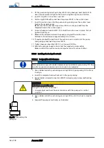


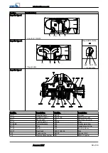


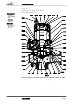

6. Lift off the pump set and adjust the axial clearance to 0.3 ± 0.1 mm.
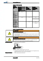
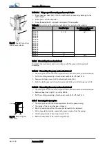
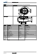
7.5.2.3.2 Design with wear plate
✓
The shaft, rolling element bearings, mechanical seal and impeller have been
assembled properly.
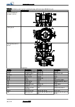
0.4
+0.2
mm
914.12
412.34
914.24
135
412.33
230
101
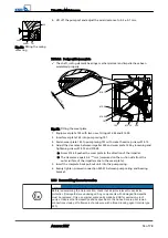
Fig. 33: Fitting the wear plate
1. Equip wear plate 135 with two new O-rings 412.33 and 412.34.
2. Insert wear plate 135 into pump casing 101.
3. Fasten wear plate 135 to pump casing 101 with socket head cap screws 914.12.
4. Adjust the clearance between impeller 230 and wear plate 135 by loosening and
tightening screws 914.12 and 914.24.
⇨
Screw 914.24 pushes the wear plate in the direction of the impeller.
⇨
The clearance equals 0.4
+0.2
mm (measured on the suction side from the
outer surface of the impeller vane to the wear plate).
5. Insert the complete back pull-out unit into the pump casing.
6. Evenly tighten screwed connection 920.01 between pump casing and bearing
bracket.
7.5.3 Reassambling the motor section
NOTE
Before reassembling the motor section, check that all joints relevant to explosion
protection (flamepaths) are undamaged. Any components with damaged flamepaths
must be replaced. Only use original spare parts made by KSB for explosion-proof
pumps. Observe the flamepath positions specified in the Annex. Secure all screwed
connections closing off a flameproof enclosure with a thread-locking agent (Loctite type
243).
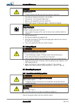
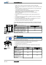
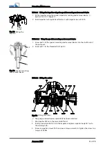
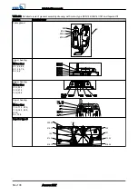
502
904.01 101
230
A
Fig. 32: Fitting the casing
wear ring
7 Servicing/Maintenance
Amarex KRT
53 of 78
Содержание Amarex KRT
Страница 77: ......


