Krom Schroder DL A Series Скачать руководство пользователя страница 2

DL..A, DL..K · Edition 02.22

EN-2

2 CHeCKInG tHe UsAGe

DL 1,5–3A, DL 3K, DL 5–150A, DL 5–150K

For monitoring positive, negative or differential pres-
sures of air, flue gas or other non-aggressive gases.

This function is only guaranteed when used within the 

specified limits – see page 7 (8 Technical data). Any 
other use is considered as non-compliant. 

2.1 type code

DL


 Pressure switch for air 

1,5


 Adjusting range -0.5 – +1.5 mbar 

3


 Adjusting range 0.2–3 mbar 

5


 Adjusting range 0.4–5 mbar 

10


 Adjusting range 1.0–10 mbar 

30


 Adjusting range 2.5–30 mbar 

50


 Adjusting range 2.5–50 mbar 

150


 Adjusting range 30–150 mbar 

A


 Rp 1/4 connection, tube connection, 

hand wheel 

K


 With tube connection, hand wheel 

t


 T-product 

G


 With gold contacts 

-2


 Electrical connection via screw terminals 

(UL listed), IP 54 

-3


 Electrical connection via screw terminals, IP 54 

-4


 Electrical connection via screw terminals, IP 65 

-5


 Electrical connection via 4-pin plug, 

without socket, IP 54 

-6


 Electrical connection via 4-pin plug, with 

socket, IP 54 

-9


 Electrical connection via 4-pin plug, with 

socket, IP 65 

K2


 Red/green pilot LED for 24 V DC/AC 

t


 Blue pilot lamp for 230 V AC 

t2


 Red/green pilot LED for 110 to 230 V 

AC 

n


 Blue pilot lamp for 120 V AC 

P


 With test tapping point 

1


 With 1 test key 

2


 With 2 test keys 

A


 External adjustment 

W


 Z-angle bracket 

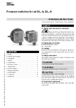
2.2 Part designations

1

2

2

3

4

Upper housing section with cover

Lower housing section

Hand wheel

M16 cable gland/1/2" NPT conduit

2.3 type label

DL

CE


2
1

3

D-49018 Osnabrück, Germany

Max. inlet pressure = withstand pressure, mains volt-
age, ambient temperature, enclosure: see type label.

3 InstALLAtIon

 CAUtIon

Please observe the following to ensure that the 
unit is not damaged during installation: 


– Dropping the device can cause permanent 

damage. In this event, replace the entire device 
and associated modules before use. 


– Use approved sealing material only. 


– Condensation must not be allowed to get into 

the housing. If possible, install pipework with an 
ascending gradient. Otherwise, there is a risk of 
icing of condensation at subzero temperatures, 
the switching point shifting or corrosion in the 
device which can lead to malfunctions. 


– Protect the connections against dirt or moisture 

in the medium to be measured or the surround-
ing air. If necessary, install a filter.


– In case of highly fluctuating pressures, install a 

damping nozzle/restrictor orifice.


– When installing outdoors, place the pressure 

switch in a roofed area and protect from direct 
sunlight (even IP 65 version). To avoid conden-
sation, the cover with pressure equalization 
element can be used. See 


– In the case of an uneven mounting surface, 

secure the pressure switch to the mounting 
plate or air duct with only two screws on the 
same side in order to avoid subjecting the 
pressure switch to mechanical stress.


– Vapours containing silicone can adversely affect 

the functioning of electrical contacts. When 
using silicone tubes, only use silicone tubes 
which have been sufficiently cured. 


– In the case of high humidity, we recommend 

using a pressure switch with gold contact due 
to its higher resistance to corrosion. Closed-cir-
cuit current monitoring is recommended under 
difficult operating conditions.


Ensure that there is sufficient installation space.


Ensure unobstructed view of the hand wheel.

Содержание DL A Series

Страница 1: ...in accordance with the regulations and standards in force These instructions can also be found at www docuthek com 1 2 Explanation of symbols 1 2 3 a b c Action Instruction 1 3 Liability We will not be held liable for damage resulting from non observance of the instructions and non com pliant use 1 4 Safety instructions Information that is relevant for safety is indicated in the instructions as fo...

Страница 2: ...re mains volt age ambient temperature enclosure see type label 3 INSTALLATION CAUTION Please observe the following to ensure that the unit is not damaged during installation Dropping the device can cause permanent damage In this event replace the entire device and associated modules before use Use approved sealing material only Condensation must not be allowed to get into the housing If possible i...

Страница 3: ...5 x 8 mm DL A Ø 3 5 x 8 mm Ø 4 x 8 mm DL 3K Ø 2 7 x 8 mm Ø 3 x 8 mm DL 3K Ø 3 5 x 8 mm Ø 4 x 8 mm DL 5 150K Ø 3 x 16 mm Ø 3 5 x 16 mm 49 5 1 9 44 5 1 7 ø 2 7 x 8 0 11 x 0 3 ø 3 5 x 8 0 14 x 0 3 ø 6 1 ø 0 24 DL A Rp DL AT NPT DL 1 5A DL 3A DL 3K 49 5 1 9 44 5 1 7 ø 2 7 x 8 ø 0 11 x 0 3 ø 3 5 x 8 ø 0 14 x 0 3 DL A Rp DL AT NPT DL 5 150A 9 5 0 4 9 5 0 4 15 5 0 6 45 1 8 54 5 2 1 6 0 2 ø 3 x 16 ø 0 11 ...

Страница 4: ...his power rating or higher power rating CAUTION To ensure that the DL is not damaged during operation note the switching capacity see page 7 8 Technical data In the case of low switching capacities such as 24 V 8 mA for example we recommend using an RC mod ule 22 Ω 1 μF in air containing silicone or oil NO C 1 µF R 22 Ω 2 NC 1 COM 3 1 Disconnect the system from the electrical power supply 2 3 4 5 ...

Страница 5: ...x DL 1 5A 0 5 1 5 50 0 1 0 16 DL 3A DL 3K 0 2 3 50 0 1 0 16 DL 3AT DL 3KT 0 3 3 150 0 1 0 16 DL 5A DL 5K 0 4 6 300 0 2 0 3 DL 5AT DL 5KT 0 5 5 300 0 2 0 3 DL 10A DL 10K DL 10AT DL 10KT 1 10 300 0 25 0 4 DL 30A DL 30K 2 5 30 300 0 35 0 9 Adjusting range1 mbar Max inlet pres sure2 mbar Mean switching differential3 mbar min max min max DL 50A DL 50K DL 50AT DL 50KT 2 5 50 300 0 8 1 5 DL 150A DL 150K ...

Страница 6: ...0430 230 V AC I 0 6 mA Order No 74920429 Pilot lamp blue 110 120 V AC I 1 2 mA Order No 74916121 230 V AC I 0 6 mA Order No 74916122 1 2 3 4 NC 1 COM 3 NO NO 2 N NO 2 NC 1 COM 3 L1 N NC 1 COM 3 NO NC 2 N NO 2 NC 1 COM 3 L1 N 7 2 Red green pilot LED for 24 V DC AC or for 110 V AC to 230 V AC 24 V DC I 16 mA 24 V AC I 8 mA Order No 74921089 110 V AC to 230 V AC Order No 74923275 1 2 3 4 NC 1 COM 3 N...

Страница 7: ...mponent Tightening torque Ncm Cover screws 65 M16 x 1 5 cable gland 50 Clamping terminal screws 80 Rp 1 8 connection on upper housing section 250 Rp 1 4 1 4 NPT connection on lower housing section 600 8 3 Electrical data Line entrance M16 x 1 5 1 2 NPT conduit clamping range diameters of 4 to 10 mm Type of connection screw terminals cable diameter 0 5 to 1 8 mm AWG 24 to AWG 13 8 3 1 Switching cap...

Страница 8: ...mage on the unit or packaging without delay Check that the delivery is complete Storage Storage temperature see page 7 8 Technical data Storage is subject to the ambient conditions described Storage time 6 months in the original packaging before using for the first time If stored for longer than this the overall service life will be reduced by the corresponding amount of extra storage time 12 DISP...

Отзывы: