background image

 TECHNICAL DATA 

5

37

OPTIWAVE 7300 C

www.krohne.com

04/2009 - 4000050002 - QS OPTIWAVE 7300 R05 en

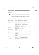
Input and output

Output signal

(Output 1)

4

20 mA HART

®

 or 3.8

20.5 mA acc. to NAMUR NE 43 

 4

Output signal

(Output 2 - optional)

4

20 mA (no HART

®

 signal) or 3.8

20.5 mA acc. to NAMUR NE 43

Resolution

±

µ

A

Temperature drift

Typically 50 ppm/K

Error signal

High: 22 mA; Low: 3.6 mA acc. to NAMUR NE 43

Approvals and certification

CE

This device fufills the statutory requirements of the EC directives. The 

manufacturer certifies successful testing of the product by applying the CE mark.

Explosion protection

Explosion protection

Explosion protection

Explosion protection

ATEX

ATEX II G 1, 1/2, 2 Ex ia IIC T6...T3;

ATEX II D 1, 1/2, 2 Ex iaD 20 or Ex iaD 20/21 or Ex iaD 21 IP6X T65

°

C...T90

°

C;

ATEX II G 1/2, 2 Ex d [ia] IIC T6...T3;

ATEX II D 1/2, 2 Ex tD[iaD] A21/20 or Ex tD[iaD] A21 IP6X T65

°

C...T90

°

C;

ATEX II G 3 Ex nA IIC T6

T3

IECEx (approval for Drop 

antennas pending)

Zone 0 Ex ia IIC T6

T3; Ex iaD 20 IP6X T65

°

C

T 90

°

C

FM or CSA - Dual Seal-approved 

(approval for Drop antennas 

pending)

NEC 500/ CEC:

NEC 500/ CEC:

NEC 500/ CEC:

NEC 500/ CEC:

Cl. I, Div. 1, Gr. ABCD (IS);

Cl. I, Div. 1, Gr. ABCD (FM only) (XP);

Cl. I, Div. 2, Gr. ABCD (XP/NI);

Cl. II, Div. 1, Gr. EFG; Cl. III (FM only) (XP);

Cl. II, Div. 1, Gr. EFG; Cl. III (IS);

Cl. II/III, Div. 2, Gr. FG (XP/NI)

NEC 505/ CEC:

NEC 505/ CEC:

NEC 505/ CEC:

NEC 505/ CEC:

Cl. I, Zone 0 AEx ia Gr. IIC (CSA: Ex ia) (IS);

Cl. I, Zone 1 AEx d [ia] Gr. IIC (XP);

Cl. I, Zone 2 AEx nA [ia] Gr. IIC (CSA: Ex nA [ia]) (IS)

NEPSI  (approval for Drop 

antennas pending)

Ex dia IIC T3

T6; Ex ia IIC T3

T6

WHG  (approval for Drop 

antennas pending)

Certificate Z-65.16-425. In conformity with the German Federal Water Act, 

§

9

Other standards and approvals

Other standards and approvals

Other standards and approvals

Other standards and approvals

EMC

EMC Directives 2004 / 108 / EC and 93 / 68 / EEC in conjunction with 

EN 61326-1 (2006).

LVD

Low-Voltage Directives 2006 / 95 / EC and 93 / 68 / EEC in conjunction with 

EN 61010-1 (2001).

NAMUR

NAMUR NE 21 Electromagnetic Compatibility (EMC) of Industrial Process and 

Laboratory Control Equipment

NAMUR NE 43 Standardization of the Signal Level for the Failure Information of 

Digital Transmitters

1

Hastelloy

®

 is a registered trademark of Haynes International, Inc.

2

Kalrez

®

 is a registered trademark of DuPont Performance Elastomers L.L.C.

3

Metaglas

®

 is a registered trademark of Herberts Industrieglas, GMBH & Co., KG

4

HART

®

 is a registered trademark of the HART Communication Foundation

QS_OPTIWAVE7300_en_090528_4000050002_R05_web.book  Page 37  Friday, May 29, 2009  4:01 PM

Содержание OPTIWAVE 7300

Страница 1: ...asurement of liquids OPTIWAVE 7300 C OPTIWAVE 7300 C OPTIWAVE 7300 C OPTIWAVE 7300 C Quick Start Quick Start Quick Start Quick Start KROHNE 04 2009 4000050002 QS OPTIWAVE 7300 R05 en QS_OPTIWAVE7300_e...

Страница 2: ...install a device with a threaded connection 21 2 9 3 How to attach antenna extensions 23 2 9 4 How to turn or remove the signal converter 24 2 9 5 How to attach the weather protection to the device 2...

Страница 3: ...CONTENTS 3 www krohne com 04 2009 4000050002 QS OPTIWAVE 7300 R05 en OPTIWAVE 7300 C 6 Notes 38 QS_OPTIWAVE7300_en_090528_4000050002_R05_web book Page 3 Friday May 29 2009 4 01 PM...

Страница 4: ...of the operator s plant INFORMATION These instructions contain important information for the handling of the device CAUTION Installation assembly start up and maintenance may only be performed by app...

Страница 5: ...o the local office of the manufacturer INFORMATION Check the packing list to check if you received completely all that you ordered INFORMATION Look at the device nameplate to ensure that the device is...

Страница 6: ...p antenna 1 Signal converter and antenna in compact version 2 Antenna extensions option and o ring for each antenna extension 3 Quick Start 4 CD ROM including Handbook Quick Start Technical Datasheet...

Страница 7: ...rer Figure 2 3 Visual check 1 Device nameplate for more data refer to the handbook 2 Process connection data size and pressure rating material reference and heat number 1 INFORMATION Look at the devic...

Страница 8: ...ot keep the device in a vertical position This will damage the antenna and the device will not measure correctly Figure 2 4 Storage conditions 1 When you put the device into storage do not keep it in...

Страница 9: ...s The devices are tested for vibration and agree with EN 50178 and IEC 60068 2 6 To make sure that you install the device quickly easily and safely prepare the installation as given in the instruction...

Страница 10: ...perature for operation of the display 20 60 C 4 140 F If the ambient temperature is not between these limits the display screen switches off automatically 3 Ambient temperature Non Ex devices 40 80 C...

Страница 11: ...nozzle from the tank wall 1 7 x tank height Maximum distance of nozzle from the tank wall 1 3 x tank diameter 6 Minimum distance of nozzle from the tank wall 1 10 x tank height Maximum distance of no...

Страница 12: ...dar level meter can be operated in a tank Figure 2 8 Product inlets 1 The device is in the correct position 2 The device is too near to the product inlet Figure 2 9 More than 1 FMCW radar level meter...

Страница 13: ...llation recommendations 1 Do not tilt the device more than 2 2 If there are too many obstacles in the radar beam do an empty spectrum scan refer to the handbook or install a by pass chamber or stillin...

Страница 14: ...ments for a stilling well 2 Recommendations for tanks that have one or more liquids without foam 3 Air circulation hole 4 Maximum level of the liquid 5 Liquid circulation hole above the maximum level...

Страница 15: ...ating roofs If the device must be installed on a tank with a floating roof install it in a stilling well Figure 2 12 Floating roofs 1 Sediment 2 Support fixtures 3 Stilling well 4 Floating roof 5 Prod...

Страница 16: ...AUTION If the device is installed in horizontal cylindrical tank that contains a high dielectric constant liquid without a stilling well do not put it on the tank centerline This will cause multiple r...

Страница 17: ...l of the stilling well 2 5 mm 0 1 for a high dielectric constant liquid 3 Sudden change in well diameter 1 mm 0 04 CAUTION Installation requirements The bypass chamber must be electrically conductive...

Страница 18: ...ntaining more than one liquid The top process connection of the bypass chamber must be above the maximum level of liquid The bottom process connection of the bypass chamber must be below the lowest me...

Страница 19: ...re the flange on the nozzle is level Make sure that you use the applicable gasket for the flange dimensions and the process Align the gasket correctly on the flange facing of the nozzle Lower the ante...

Страница 20: ...Lower the antenna carefully into the tank Do not attach to the tank yet Attach the antenna and the antenna locking screw Lower the antenna carefully into the tank Tighten the flange bolts Attach the...

Страница 21: ...level Make sure that you use the applicable gasket for the connection dimensions and the process Align the gasket correctly Lower the antenna carefully into the tank Turn the threaded connection on t...

Страница 22: ...connection of the device is smaller than the process connection on the tank Make sure the tank connection is level Use a plate with a slot or a different applicable procedure to adapt the device to t...

Страница 23: ...ing distance value in the user interface i Minimum blocking distance antenna length antenna extension length x number of extensions 0 1 m 4 Horn antenna antenna extensions Figure 2 20 Horn antenna how...

Страница 24: ...mber of extensions If you attach more extensions than were initially ordered change the blocking distance value in the user interface i Minimum blocking distance antenna length antenna extension lengt...

Страница 25: ...he device Equipment needed Device Weather protection option 10 mm wrench not supplied The overall dimensions of the weather protection are in Dimensions and weight in the handbook Loosen the bracket n...

Страница 26: ...to the keyhole at the front of the weather protection Turn the screwdriver counterclockwise Pull the top of weather protection up and forward i This will open the weather protection Figure 2 24 How to...

Страница 27: ...on the electrical components of the measuring device may only be carried out by properly trained specialists INFORMATION Look at the device nameplate to ensure that the device is delivered according...

Страница 28: ...r HART communication 3 Output 1 14 30 VDC for an output of 22 mA at the terminal 4 Output 2 10 30 VDC for an output of 22 mA at the terminal DANGER For electrical data for Ex i applications refer to t...

Страница 29: ...al code The cables are in a loop in front of the device 1 so water does not go into the housing Tighten the cable feedthroughs 2 Close unused cable feedthroughs with dummy plugs 3 INFORMATION The devi...

Страница 30: ...ting concept You can read measurements and configure the device with A digital display screen optional A connection to a system or PC with PACTware You can download the Device Type Manager DTM file fr...

Страница 31: ...isplayed This will explain what the menu is and what the parameters do Press and U Esc at the same time to go back to the menu If you do not touch the display for another 30 seconds the message is sho...

Страница 32: ...nication standard for sending information between the system and the field device This standard agrees with IEC PAS 62453 Field devices are easily integrated Installation is supported by a user friend...

Страница 33: ...e and read process data Store and read diagnostic status information Help plan preventive maintenance to reduce a plant s downtime to a minimum The DD file is given on the CD ROM supplied with the dev...

Страница 34: ...s Integrated LCD display with sun cover 20 60 C 4 140 F if the ambient temperature is not in these limits the display switches off 2nd current output PTFE PP flange plate protection for Drop antennas...

Страница 35: ...pplementary operating instructions or approval certificates Drop antenna PTFE Drop antenna PTFE Drop antenna PTFE Drop antenna PTFE 40 150 C 58 300 F according to the temperature limits of the gasket...

Страница 36: ...F Kalrez 6375 20 200 C 4 390 F EPDM 40 C 150 C 40 300 F 2 Feedthrough Standard PEI 40 200 C 40 390 F Option Metaglas 30 200 C 22 390 F for horn antennas only 3 Weather protection Option Stainless ste...

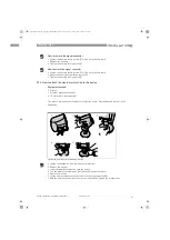
Страница 37: ...y XP Cl I Div 2 Gr ABCD XP NI Cl II Div 1 Gr EFG Cl III FM only XP Cl II Div 1 Gr EFG Cl III IS Cl II III Div 2 Gr FG XP NI NEC 505 CEC NEC 505 CEC NEC 505 CEC NEC 505 CEC Cl I Zone 0 AEx ia Gr IIC CS...

Страница 38: ...6 NOTES 38 OPTIWAVE 7300 C www krohne com 04 2009 4000050002 QS OPTIWAVE 7300 R05 en Notes QS_OPTIWAVE7300_en_090528_4000050002_R05_web book Page 38 Friday May 29 2009 4 01 PM...

Страница 39: ...NOTES 6 39 OPTIWAVE 7300 C www krohne com 04 2009 4000050002 QS OPTIWAVE 7300 R05 en QS_OPTIWAVE7300_en_090528_4000050002_R05_web book Page 39 Friday May 29 2009 4 01 PM...

Страница 40: ...gas industry Measuring systems for sea going tankers Head Office KROHNE Messtechnik GmbH Co KG Ludwig Krohne Str 5 D 47058 Duisburg Germany Tel 49 0 203 301 0 Fax 49 0 203 301 10389 info krohne de KRO...

Отзывы: