


OPERATION
5
17
OPTISYS CL 1100
www.krohne.com
03/2016 - 4002492302 - MA OPTISYS CL 1100 R03 en
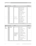
5.1 Menu mode structure
INFORMATION!
The following table just presents an overview. When programming the device, always consult the
function tables additionally as they contain further information!
Only the sensor relevant menus are shown in the following tables. For detailed information
about the general setting refer to the signal converter manual.
Measuring
mode
Main menu
Submenu
Parameter
3 or 4
pages,
scrolling
with
↓
or
↑
> 2.5 s
^
A quick setup
A quick setup
A quick setup
A quick setup
>
^
A9 product cal.A
process input A
product
calibration
(Cl
2
/ClO
2
/O
3
)
>
^
A9.1 temp.comp.
>
^
For further
information
see function
tables.
A9.4 pH compensation
A9.6 start calib.
A9.7 stored value
A9.8 reference
A12 ORP
calibration B
Only if switched
Only if switched
Only if switched
Only if switched
to ORP!
to ORP!
to ORP!
to ORP!
process input B
ORP calibration
(for 2 channel
version; refer to
pH/ORP sensor
documentation
for further
information)
A13 pH cal. B
process input B
pH calibration
(for 2 channel
version; refer to
pH/ORP sensor
documentation
for further
information)
A13.1 temp.comp.
↓↑
↓↑
↓↑
↓↑
> 2.5 s
^
B test
B test
B test
B test
>
^
B1 sim.process
inp.A
>
^
B1.1 temperature
>
^
For further
information
see function
tables.
B1.4 conc.absolute
B2 sim.process
inp.B
B2.1 temperature
B2.5 ORP
Only if switched to ORP!
Only if switched to ORP!
Only if switched to ORP!
Only if switched to ORP!
(for 2 channel version; refer to
pH/ORP sensor documentation
for further information)
B2.7 pH
(for 2 channel version; refer to
pH/ORP sensor manual for
further information)
B3 simulation I/O
B3.1 current out A
B3.2 current out B
B3.3 current out C
B3.4 simulation R1
B3.5 simulation R2
B3.6 simulation R3


