background image

 CONTENTS


www.krohne.com

04/2008 • 4000243601

OPTIFLUX 2070

1 Safety 

instructions......................................................................... 4

1.1 Intended use......................................................................................................... 4
1.2 Safety instructions from the manufacturer......................................................... 4

1.2.1

Disclaimer.................................................................................................................. 4

1.2.2

Information concerning the documentation ............................................................. 4

1.2.3

Display conventions ................................................................................................... 5

1.3 Safety instructions for the operator .................................................................... 5

1.3.1

Transportation, handling and using instruction for batteries .................................. 6

2 Instrument 

description.................................................................. 7

2.1 Scope of delivery .................................................................................................. 7
2.2 Instrument description ........................................................................................ 7
2.3 Nameplate............................................................................................................ 8

3 Installation..................................................................................... 9

3.1 Pre-installation requirements............................................................................. 9
3.2 General installation notes.................................................................................... 9
3.3 Storage ................................................................................................................. 9
3.4 Transport.............................................................................................................. 9
3.5 Installation requirements .................................................................................. 10

3.5.1

Inlet and outlet......................................................................................................... 10

3.5.2

Mounting position and flange deviation .................................................................. 10

3.5.3

Vibration................................................................................................................... 11

3.5.4

Magnetic field .......................................................................................................... 11

3.5.5

Bends ....................................................................................................................... 11

3.5.6

Open discharge ........................................................................................................ 12

3.5.7

T-section .................................................................................................................. 12

3.5.8

Control valve ............................................................................................................ 13

3.5.9

Pump........................................................................................................................ 13

3.5.10 Grounding ................................................................................................................ 14

3.6 Installation ......................................................................................................... 14
3.7 Mounting of converter........................................................................................ 16

3.7.1

Mounting of IFC 070 F.............................................................................................. 16

4 Electrical 

connections ................................................................. 17

4.1 Safety instructions ............................................................................................. 17
4.2 Terminal assignment of IFC 070........................................................................ 17
4.3 Signal cable........................................................................................................ 18
4.4 Cable connection for field version ..................................................................... 19

4.4.1

Flow sensor side...................................................................................................... 19

4.4.2

Converter side ......................................................................................................... 20

5 Start-up ....................................................................................... 21

5.1 Connection of battery......................................................................................... 21

Содержание OPTIFLUX 2070

Страница 1: ...Battery powered electromagnetic flowmeter OPTIFLUX 2070 OPTIFLUX 2070 OPTIFLUX 2070 OPTIFLUX 2070 Handbook Handbook Handbook Handbook...

Страница 2: ...tallation requirements 9 3 2 General installation notes 9 3 3 Storage 9 3 4 Transport 9 3 5 Installation requirements 10 3 5 1 Inlet and outlet 10 3 5 2 Mounting position and flange deviation 10 3 5 3...

Страница 3: ...0 5 1 1 Internal battery 21 6 Operation 22 6 1 Display and operating elements 22 6 2 Menu of IFC 070 converter 22 7 Service 26 7 1 Replacement of battery 26 8 Technical data 28 8 1 Technical data 28 8...

Страница 4: ...o some or all of the above disclaimer exclusions or limitations Any product purchased from the manufacturer is warranted in accordance with the relevant product documentation and our Terms and Conditi...

Страница 5: ...rding such warnings can result in serious health damage damage to the device itself or to parts of the operator s plant DANGER This symbol designates safety advice on handling electricity CAUTION Thes...

Страница 6: ...temperature range or incinerate the battery Do not crush puncture or open cells or disassemble battery packs Do not weld or solder to the body of the battery Do not expose contents of battery to wate...

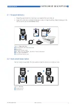
Страница 7: ...mage to the carrier and to your local KROHNE office 2 2 Instrument description Two versions are available You received a compact version or a remote version Figure 2 1 Scope of delivery 1 OPTIFLUX 207...

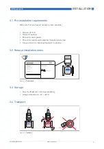
Страница 8: ...2008 4000243601 2 3 Nameplate Figure 2 3 Nameplate OPTIFLUX 2070 1 Manufacturer 2 Voltage information 3 Material of wetted parts 4 Meter constant 5 Serial number 6 Device type CAUTION Check on the de...

Страница 9: ...e Allen key 4 mm Philips screwdriver Wrench for cable glands Wrench for wall mounting bracket remote version only Torque wrench for installing flowmeter in pipeline 3 2 General installation notes 3 3...

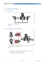
Страница 10: ...5 2 Mounting position and flange deviation Mount flowmeter either with converter aligned upwards or downwards Install flowmeter in line with the pipe axis Pipe flange faces must be parallel to each ot...

Страница 11: ...rohne com 04 2008 4000243601 3 5 3 Vibration 3 5 4 Magnetic field 3 5 5 Bends CAUTION Max permissible deviation of pipe flange faces Lmax Lmin 0 5 mm Figure 3 5 Vibration Figure 3 6 Magnetic field Fig...

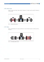
Страница 12: ...3601 3 5 6 Open discharge Install meter on a lowered section of the pipe to ensure a full pipe condition through the meter 3 5 7 T section Figure 3 8 Preferable installation close to open discharge Fi...

Страница 13: ...all control valves downstream of flowmeter in order to avoid cavitation or distortion of flow profile 3 5 9 Pump Never install flowmeter at a pump suction side in order to avoid cavitation or flashing...

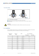
Страница 14: ...elines with internal coating and non conductive pipelines Grounding with grounding rings 3 Grounding rings CAUTION The grounding of the flowmeter provides a stable and accurate measurement Nominal siz...

Страница 15: ...rque given in tables before Nominal size inch Flange class lbs Bolts Max torque Nm Polypropylene Hardrubber 2 150 4 5 8 24 23 3 150 4 5 8 43 39 4 150 8 5 8 34 31 5 150 8 3 4 48 43 6 150 8 3 4 61 51 8...

Страница 16: ...7 Mounting of converter 3 7 1 Mounting of IFC 070 F Mount IFC 070 F with mounting plate on wall or standpipe Keep distance between sensor and signal converter as short as possible Observe length of t...

Страница 17: ...fety instructions 4 2 Terminal assignment of IFC 070 WARNING Observe the regional occupational health and safety regulations without fail Only work on the device electrics if you are appropriately tra...

Страница 18: ...5 24 VDC P 100 mW Status output passive Status output passive Status output passive Status output passive I 10 mA U 5 24 VDC P 100 mW 4 3 Signal cable Figure 4 2 Terminal assignment 1 Status output 1...

Страница 19: ...clamp the brown cable to terminal 7 and the white to terminal 8 Connect the shield to terminal 1 the purple cable to terminal 2 and the blue to terminal 3 Figure 4 3 Cable connection at flow sensor si...

Страница 20: ...to terminal 7 and the white to terminal 8 Connect the shield to terminal 1 the purple cable to terminal 2 and the blue to terminal 3 Figure 4 4 Cable connection at converter side 1 cable length 16 cm...

Страница 21: ...the battery connector to the internal connector in the IFC 070 converter check that the display lights up replace the cover tighten the 4 Allen bolts replace the blue protection cap CAUTION Please con...

Страница 22: ...o enter the value i the value flashes use the Z and V key to change the value hold the Z key for 3 seconds to confirm the new value to leave the programming mode hold the V key for 3 seconds to store...

Страница 23: ...gether with the reset button for 6 seconds as shown in the graph below Use a small screwdriver for the reset button Display starts with the menu beginning with menu no 12 Go to menu no 13 and change 1...

Страница 24: ...flow cut off 20 0 5 10 20 mm s Below value no measurement 28 Time constant flow reading 2 1 fast 2 normal 3 slow Timeconstant of display 29 Factory calibration comm mode 0 0 No 1 Yes For factory use...

Страница 25: ...ters reset 88888 Set to 00000 After reset display value is back to 88888 Confirm with for 3 seconds 71 Counters Run Stop 1 0 stop 1 run 72 All Errors Reset 0 Set to 1 After reset display value is back...

Страница 26: ...e cover Disconnect the connector of the battery Remove the battery holder by pulling it upwards Remove the battery from the holder Insert the new battery in the holder Replace the holder Fasten the ba...

Страница 27: ...hrough the available positions with the V key to position 74 and check the battery capacity important for battery life indication Go to position 75 and enter 1 reset battery counter i Battery capacity...

Страница 28: ...ange 0 12m s 0 39ft s Max deviation under reference conditions 1 0 5 of measured flowrate value 2mm s Repeatibility 0 3 v 0 5 m s 1 5 ft s Process conditions Potable water Surface water clean ground w...

Страница 29: ...less steel 1 4571 AISI 316 Ti Titanium Grounding rings Hastelloy C4 Stainless steel 1 4571 AISI 316 Ti Titanium Flanges Steel 1 0460 C 22 8 Steel 1 0038 RSt37 2 Stainless steel 1 4404 AISI 316 L Stain...

Страница 30: ...Y vs flow velocity X m s Nominal diameter VN14 VN15 ASME inch 2 2 1 2 3 4 5 6 8 10 12 14 16 18 20 24 DN mm 50 65 80 100 125 150 200 250 300 350 400 450 500 600 Versions Compact Separate Electrical con...

Страница 31: ...20 x 1 5 Optional 1 2 NPT PF 1 2 Materials Converter housing Die cast aluminium polyurethane coated In and output Outputs 2 passive pulse outputs for remote totalising f 500 Hz I 10 mA U 5 24 VDC P 10...

Страница 32: ...1 Separate flow sensor OPTIFLUX 2000 F 5 90 40 65 Compact with IFC 070 OPTIFLUX 2070 C 5 90 40 65 1 Polypropylene available for DN 50 150 Process F Ambient F min max min max Hardrubber Separate flow s...

Страница 33: ...TECHNICAL DATA 8 33 OPTIFLUX 2070 www krohne com 04 2008 4000243601 8 2 Dimensions and Weights OPTIFLUX 2070 C OPTIFLUX 2000 F IFC 070 F T W H 070 W Tbox c a 175mm 310mm 335mm...

Страница 34: ...10 600 568 565 646 738 103 450 10 600 618 615 696 788 113 500 10 600 671 670 749 841 132 600 10 600 781 780 859 951 167 Flanges acc ASME B16 5 Dimensions for 150 lbs flanges inch Approx weight lbs DN...

Страница 35: ...150 200 179 152 257 349 15 3 150 200 204 190 5 282 374 19 4 150 250 241 228 6 319 411 25 5 150 250 268 254 346 438 29 6 150 300 297 279 4 375 467 36 8 150 350 362 342 9 440 532 45 10 150 400 414 406 4...

Страница 36: ...dia India India India Krohne Marshall Ltd A 34 35 M I D C Industrial Area H Block Pimpri Poona 411018 Phone 91 0 202 744 2020 Fax 91 0 202 744 2020 pcu vsnl net Iran Iran Iran Iran KROHNE Liaison Offi...

Отзывы: