background image

 DEVICE DESCRIPTION 

2

7

DK37/M8 - H250/M8

www.krohne.com

11/2017 - 4002616802 - AD DK37 NEPSI Ex ia R02 en

Type series DK37

Type series DK37

Type series DK37

Type series DK37
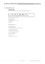
The safety description code * consists of the following elements:

* positions which are not needed are omitted (no blank positions)

1  

Type series of measuring unit DK

2  

Type series of signal converter 37

3  

Type series of indicators

M8M - Mechanical indicator
M8E - Electronic indicator

4  

Design of indicator housing 

without - Indicator housing in PPS
R - Indicator housing in stainless steel

5  

Optional differential pressure regulator

RE - Inlet pressure regulator
RA - Outlet pressure regulator

6  

Limit switch (M8M version)

K1 - One limit switch
K2 - Two limit switches

Содержание DK37/M8

Страница 1: ...e of protection Intrinsic Safety i DK37 M8 H250 M8 DK37 M8 H250 M8 DK37 M8 H250 M8 DK37 M8 H250 M8 Supplementary Instructions Supplementary Instructions Supplementary Instructions Supplementary Instru...

Страница 2: ...ing 8 2 4 Flammable products 9 2 5 Device category 9 2 6 Protection types 10 2 7 Ambient temperature temperature classes product temperature 11 2 8 Electrical data 13 3 Installation 14 3 1 Mounting 14...

Страница 3: ...s GB 3836 1 2010 Explosive atmospheres Part 1 Equipment General requirements GB 3836 4 2010 Explosive atmospheres Part 4 Equipment protection by intrinsic safety i The certificate number is This certi...

Страница 4: ...ssembly installation start up and maintenance may only be performed by personnel trained in explosion protection CAUTION The operator or his agent is responsible for observing any additional standards...

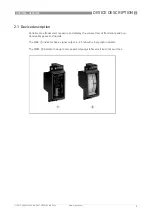
Страница 5: ...02 en 2 1 Device description Variable area flowmeters measure and display the volume flow of flammable and non flammable gases and liquids The M8E 1 indicator has a signal output 4 20 mA with a bargra...

Страница 6: ...g unit H250 2 Materials versions RR stainless steel C PTFE or PTFE with ceramic liner HC Hastelloy Ti Titanium F Food 3 Type series of indicators M8 Indicator M8 4 Design of indicator M8 MG Mechanical...

Страница 7: ...eded are omitted no blank positions 1 Type series of measuring unit DK 2 Type series of signal converter 37 3 Type series of indicators M8M Mechanical indicator M8E Electronic indicator 4 Design of in...

Страница 8: ...Figure 2 1 Example of nameplate 1 Product designation 2 Manufacturer name and address 3 Sizing data temperature pressure rating 4 PED data 5 Marking according to NEPSI and permissible ambient tempera...

Страница 9: ...lack of key safety data for the interior of the measuring unit 2 5 Device category Variable area flowmeters are designed in accordance with GB 3836 1 2010 and GB 3836 4 2010 for use in zone 1 The ins...

Страница 10: ...the following information The marking contains the following information Ex ia Ex ia Ex ia Ex ia Explosion protection type intrinsic safety level of protection ia IIC IIC IIC IIC Gas group suitable fo...

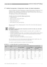
Страница 11: ...e to differing boundary conditions e g liner materials Here the user should consult the technical data sheet The maximum product temperature is outlined in the following tables DK37 M8 permissible pro...

Страница 12: ...mperature maximum value Type H250 M8EG Type H250 M8MG at 64 mW Type H250 M8MG at 169 mW C F C F C F C F T6 40 104 85 185 85 185 40 104 50 122 85 185 60 140 85 158 T5 40 104 100 212 100 212 100 212 50...

Страница 13: ...ture H250 M8EG DK37 M8E Signal output 4 20 mA 40 C 40 F H250 M8MG DK37 M8M SJ2 S1N SC2 N0 25 C 13 F H250 M8MG DK37 M8M I7S2002 N SJ2 SN 40 C 40 F Maximum values Device version Ui V Ii mA Pi mW Ci nF L...

Страница 14: ...th the requirements of the manual of the associated apparatus The maximum values for connection to a certified associated apparatus are shown in the section Electrical data The correlation between the...

Страница 15: ...sulated against each other and against ground test voltage 500 Veff Lay cables so as to ensure that there is sufficient distance between surfaces of the measuring unit and the connecting cable Supplie...

Страница 16: ...lt in electrical equipment is supplied via the signal circuits 4 3 Inputs outputs The terminal assignment of the built in electrical equipment is described in the product documentation The signal circ...

Страница 17: ...sing the ground terminal 1 The position of the ground terminal is illustrated below This connection only ensures electrostatic grounding of the device and does not meet the requirements for equipotent...

Страница 18: ...inoperable during operation Adjusting the limit switch and operating the display during operation is permitted To do so remove the housing cover Close the housing cover immediately after the adjustmen...

Страница 19: ...the display Replacing the display Replacing the display Due to the modular design of the variable area flowmeters from a safety perspective the complete display can be replaced with identical spare p...

Страница 20: ...vices Head Office KROHNE Messtechnik GmbH Ludwig Krohne Str 5 47058 Duisburg Germany Tel 49 203 301 0 Fax 49 203 301 10389 info krohne com KROHNE 11 2017 4002616802 AD DK37 NEPSI Ex ia R02 en Subject...

Отзывы: