


66
Setting the High Calibration Point
Ensure that the meter is properly installed and is operating correctly.
Circulate the high density fluid at a high flow rate for a few minutes to ensure that no air bubbles
remain inside the meter.
Adjust flow rate to the typical rate for the application. (50% of rated flow is ideal). If operating at
temperatures other than ambient maintain these conditions for about 20 minutes so that the
meter can stabilise. (G+ meters 100G and bigger need only be left 5 minutes but 20 minutes is
optimum).
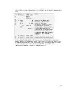
On the menus go to menu 3.9.10 D. REF. HIGH and repeat the procedure as for the LOW
density point. (note WATER and not AIR will be the option for the density type in this case.)
Note : If on leaving functions 3.9.10 or 3.9.11 the CALIB. ERR message is displayed this means
that the meter was unable to calculate realistic values for CF1 and CF2. Press
↵
to continue.
This error may be caused by a number of factors. Please check the following:
Check initial values of CF1 and CF2, these should be the same or similar to the values printed
on the data plate. If these are vastly different re-enter the values from the data plate and repeat
the calibrations.
Check CF3 and CF4 are as printed on the data plate.
Ensure that both calibration points were carried out with different density fluids and that the
correct densities were entered on the display.
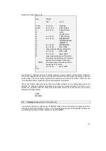
Reviewing the Calibration settings.
After successfully calibrating the density it is recommended that the new data is recorded on the
table below. CF1 and CF2 can be found from menus Fct. 3.9.1 and 3.9.2.
Density Calibration Data
Serial Number
Date
Primary Type
Fct. 3.9.1
CF1
Fct. 3.9.2
CF2
Fct. 3.9.3
CF3
Fct. 3.9.4
CF4
Frequency
Temperature
Strain
Density
Fct. 3.9.10
D. REF. HIGH
Hz
°C/°F
Ω
Fct. 3.9.11
D. REF. LOW
Hz
°C/°F
Ω
Содержание CORIMASS MFM 4085 K/F
Страница 26: ...26 4 2 Krohne Operating Concept...
Страница 54: ...54 Current output characteristics...
Страница 101: ...101 10 4 Block diagram of Converter MFC 085...


