background image

ENGLISH

5

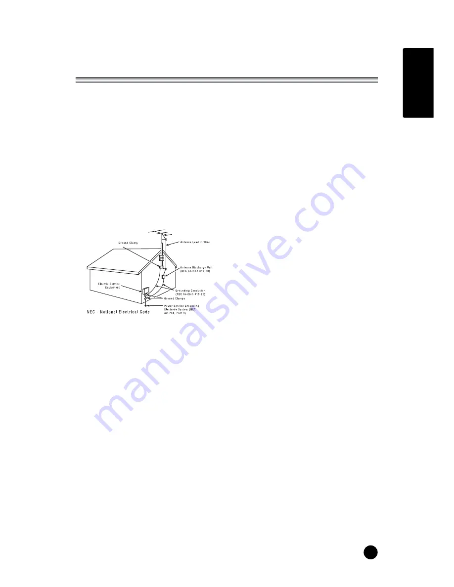
14. Outdoor Antenna Grounding

If an outside antenna or cable system is
connected to the product, be sure the antenna or
cable system is grounded so as to provide some
protection against voltage surges and built-up
static charges. Article 810 of the National
Electrical Code (U.S.A.), ANSI/NFPA 70 provides
information with regard to proper grounding of
the mast and supporting structure, grounding of
the lead-in wire to an antenna discharge unit, size
of grounding conductors, location of antenna-
discharge unit, connection to grounding
electrodes, and requirements for the grounding
electrode.

Example of Grounding According to National
Electrical Code Instructions

15. Lightning

For added protection for this product (receiver)
during a lightning storm, or when it is left
unattended and unused for long periods of
time, unplug it from the wall outlet and
disconnect the antenna or cable system. This
will prevent damage to the product due to
lightning and power-line surges.

16. Power Lines

An outside antenna system should not e
located in the vicinity of overhead power lines
or other electric light or power circuits, or where
it can fall into such power lines or circuits.
When installing an outside antenna system,
extreme care should be taken to keep from
touching such power lines or circuits, as
contact with them might be fatal.

17. Overloading

Do not overload wall outlets and extension
cords as this can result in a risk of fire or
electric shock.

18. Object and Liquid Entry

Never push objects of any kind into this
product through openings as they may touch
dangerous voltage points or short-out parts
that could result in a fire or electric shock.
Never spill liquid of any kind on the product.

19. Servicing

Do not attempt to service this product yourself as
opening or removing covers may expose you to
dangerous voltage or other hazards. Refer all
servicing to qualified service personnel.

20. Damage Requiring Service

Unplug this product from the wall outlet and refer
servicing to qualified service personnel under the
following conditions:

a. If the power-supply cord or plug is damaged.
b. If liquid has been spilled, or objects have fallen  

into the product.

c. If the product has been exposed to rain or water.
d. If the product does not operate normally by f     

ollowing the operating instructions. Adjust only  

those controls that are covered by the operating
instructions as an improper adjustment of other  

controls may result in damage and will often   

require extensive work by a qualified technician  

to restore the product to its normal operation.

e. If the product has been dropped or the cabinet  

has been damaged.

f. If the product exhibits a distinct change in  

performance.

21. Replacement Parts

When replacement parts are required, be sure the
service technician has used replacement parts
specified by the manufacturer or have the same
characteristics as the original part. Unauthorized
substitutions may result in fire, electric shock, or
other hazards.

22. Safety Check

Upon completion of any service or repairs to this
product, ask the service technician to perform
safety checks to determine that the product is in
proper operating condition.

23. Wall Mounting

The product should be mounted to a wall only as
recommended by the manufacturer. The product
may slide or fall, causing serious injury to a child or
adult, and serious damage to the product.

24. Heat

The product should be situated away from heat
sources such as radiators, heat registers, stoves, or
other products (including amplifiers) that produce
heat.

IMPORTANT SAFETY INSTRUCTIONS

Содержание KR-320T

Страница 1: ...ENGLISH Owner s Manual Model KR 320T 32 WIDE LCD Color TV MONITOR ...

Страница 2: ......

Страница 3: ...e to radio or television reception which can be determined by turning the equipment off and on the user is encouraged to try to correct the interference by one or more of the following measures Reorient or relocate the receiving antenna Increase the separation between the equipment and receiver Connect the equipment into an outlet on a circuit different from that to which the receiver is connected...

Страница 4: ...ounting of the product should follow the manufacturer s instructions and should use a mounting accessory recommended by the manufacturer 8 Transporting Product A product and cart combination should be moved with care Quick stops excessive force and uneven surfaces may cause the product and cart combination to overturn 9 Attachments Do not use attachments not recommended by the product manufacturer...

Страница 5: ...r spill liquid of any kind on the product 19 Servicing Do not attempt to service this product yourself as opening or removing covers may expose you to dangerous voltage or other hazards Refer all servicing to qualified service personnel 20 Damage Requiring Service Unplug this product from the wall outlet and refer servicing to qualified service personnel under the following conditions a If the pow...

Страница 6: ......

Страница 7: ...Program Iist 16 Picture Control 17 Manual picture control 17 Auto picture control 17 Sound Control 18 Captions 19 Parental Control 20 22 Other functions 23 24 TV VIDEO COMPONENT and S VIDEO mode 23 Auto sleep 23 Blue Back 23 Auto Wide 23 Sleep timer 24 SAP 24 PIP function 24 External Equipment Connection 25 26 Antenna Connection 25 COMPONENT INPUT 25 A V INPUT 25 S VIDEO INPUT 26 DTV INPUT 26 Head...

Страница 8: ...orrect polarity to and to 3 Replace the battery compartment cover Install two high quality 1 5V AAA alkaline batteries Don t mix old batteries with new batteries Remove batteries when you won t use the remote controller for long time Liquid leakage from old batteries may cause operation failure uNotes for using remote controller Make sure there are no objects between the remote controller and its ...

Страница 9: ...s switched on Illuminates in blinked when the power save mode only PC mode 7 Remote control sensor Accepts the IR signal of remote controller 1 PC ANALOG IN D SUB 2 PC DIGITAL IN DVI I 3 PC AUDIO IN Connect the audio cable from the PC to the PC AUDIO IN of the set 4 H P Headphone out Connect a headphone to this socket 5 S VIDEO IN Connect the output of an S VIDEO VCR to the S VIDEO input Connect t...

Страница 10: ...annel numbers 4 PSM Picture Status Memory Recalls your preferred picture setting 5 SSM Sound Status Memory Recalls your preferred sound setting 6 SAP Adjusts the MTS stereo Mono SAP 7 MENU Displays a main menu 8 TV AV Selects TV VIDEO COMPONENT S VIDEO PC ANALOG PC DIGITAL or DTV mode Clears the menu from the screen 9 SLEEP Sets the sleep timer 10 TV PC Selects TV PC ANALOG or PC DIGITAL DTV mode ...

Страница 11: ...en 18 ARC Selects a screen mode 16 9 14 9 ZOOM 1 1 4 3 19 INPUT Selects the AV source of sub picture in PIP mode 20 POSITION Selects a position of PIP screen 21 SWAP Switches a main picture for sub picture in PIP mode 22 MODE Selects a PIP screen mode 16 1 9 1 double window and scan mode It s possible when a main mode is video mode 23 xCHy Selects a Channel when RF signal is displayed in PIP mode ...

Страница 12: ...number with the CHx xy y button or NUMBER buttons Volume adjustment Press the VOLÏ Ïq q button to adjust the sound level Quick view Press the Q VIEW button to view the last channel you were watching Sound mute function Press the MUTE button The sound is switched off and the mute display appears To cancel mute mode press the MUTE button again VOLÏ Ïq q SSM button or SAP button On screen menu langua...

Страница 13: ... display main menu 2 Press the CHx xy y button to select menus Picture Sound Special Setup 3 Adjust each menu with the VOLÏ Ïq q button 4 Press the MENU button to return to preceding menu 5 Press the TV AV button to finish adjusting menu CH CH VOL VOL TV AV PSM MENU TV AV Main menu Picture q Sound q Special q Setup q Picture Contrast 90 Brightness 75 Color 75 Sharpness 50 Tint 0 MENU TV AV Sound E...

Страница 14: ...se Auto Program during installation of this set 1 Press the MENU button 2 Select the Setup menu 3 Select the Auto program menu 4 Press the CHx xy y button to select Tuner mode 5 Select a Tuner mode with the VOLÏq button TV ÏqCable 6 Select the Start with the CHx xy y button 7 Press the VOLÏq button to start Auto program 8 Press the MENU button to stop Auto Program 9 Press the TV AV button to retur...

Страница 15: ...Select the Fine menu and adjust the received signal with VOLÏ Ïq q button 8 Press the CHx xy y button to select Search Press the NUMBER buttons to commence searching 9 Press the CHx xy y button to select Name Press the VOLÏ Ïq q button You can use a blank the numeric 0 to 9 and the alphabet A to Z With the VOLÏ Ïq q button you can select in the opposite direction 10 If this Channel is the one requ...

Страница 16: ...number Paging through a Program list When The set is TV mode there are 7 program table pages in which contain 69 programs and when the set is cable mode there are 13 program table pages in which contain 125 programs Pressing the CHx xy y or VOLÏ Ïq qbutton repeatedly turns the pages The channel which is a signal is indicated with a white color The channel which is a no signal is indicated with a b...

Страница 17: ...atedly to select PSM Each press of the button changes the screen display as below Dynamic Standard Mild Game User Dynamic Vivid Picture Appearance Standard Standard Picture Appearance Mild Softer Picture Appearance Game External Video Game Picture Setup User Manual Picture Setup CH CH VOL VOL TV AV PSM Selected Item Contrast Brightness Color Sharpness Tint Setting Change More darkness VOLÏ 0 100 q...

Страница 18: ...he VOLÏq button c Make appropriate sound level with the CHx xy y button d Press the MENU button to return to preceding MENU and the TV AV button to return to normal TV viewing 7 Select the Balance menu and adjust the balance of speakers 8 Select the AVL Automatic Volume Leveler menu On or Off 9 Select the Surround menu On or Off 10 Select the nVolume menu and adjust the volume from headphone 11 Pr...

Страница 19: ...om the antenna is weak The program wasn t captioned when it was produced transmitted or taped 1 Press the MENU button 2 Select the the Special menu 3 Press the CH x xy y buttons to select Caption menu 4 Press the VOL Ï Ïq qbutton select the Caption mode 5 Each time you press the VOLÏ Ïq q buttons the caption mode is displayed one by one as shown below OFF CC1 CC2 CC3 CC4 TEXT4 TEXT3 TEXT2 TEXT1 6 ...

Страница 20: ...ental Control Determine which rating you consider acceptable to the viewer For example if you choose TV PG all more restrictive ratings will be automatically blocked the viewer will not be able to see TV PG TV 14 or TV MA rated programming Do you want to block the auxiliary video source entirely Blocks the signal sent by the equipment such as a VCR connected to the TV Audio Video input jacks in th...

Страница 21: ...r preferences Set the hours you want Parental Control active Set a 4 number password Set the Lock On Off option to either on or off When the Parental Control menu is Lock On PIP picture is scrambled Parental Control Selected Item Setting Change Aux Block Source Unblocked Blocked Unblocked G and Above PG and Above PG 13 and Above R and Above NC 17 and Above X Unblocked TV G and Above TV PG and Abov...

Страница 22: ...tal Guidance Suggested Restricted viewing Restricted Viewing Hard Core Films Parental Guidance Suggested CHILDREN S CLASSIFICATIONS Grade Meaning Considered suitable for all children under 7 years old Considered suitable for children over 7 may contain Fantasy Violence Scenes Children TV Y TV Y7 Children 7 and over Grade Meaning Considered suitable for all audiences children may watch unattended S...

Страница 23: ...s of the set Alternatively you can select the TV VIDEO COMPONEN T S VIDEO PC ANALOG and PC DIGITAL DTV modes by pressing the TV AV button PC ANALOG PC connected to the D SUB in of the set PC DIGITAL PC connected to the DVI in of the set DTV DTV Set Top Box connected to the COMPONENT IN of the set Auto sleep If you select Auto sleep on the set will automatically switch itself to standby mode approx...

Страница 24: ... the language during dual language broadcast PIP Function Viewing the PIP picture Press the PIP button Press the PIP button again to turn off PIP Selecting the PIP picture mode Press the MODE button to adjust the PIP picture mode Each press the MODE button selects the 16 1 9 1 double window and multi picture mode Multi picture mode is just available when the main picture is in AV mode Moving the P...

Страница 25: ... VCR to the L MONO socket of the set COMPONENT INPUT 1 Connect the COMPONENT video output sockets Y Cb Cr of the COMPONENT to the COMPONENT INPUT sockets of the set 2 Connect the audio cable from the COMPONENT to the COMPONENT INPUT sockets of the set 3 Press the TV AV button to select COMPONENT mode 4 Press the PLAY button on the DVD The COMPONENT playback picture appears on the screen Antenna co...

Страница 26: ...e set 3 Press the TV AV button to select DTV mode S VIDEO Input If using an S VIDEO source the picture quality will be improved over a video source 1 Connect the S VIDEO output of a VCR to the S VIDEO input on the TV 2 Connect the audio cables from the S VIDEO VCR to the L MONO R inputs on the TV 3 Select S VIDEO mode by pressing the TV AV button repeatedly 4 Press the PLAY button on the VCR The V...

Страница 27: ...u to remove any horizontal noise and clear or sharpen the image of characters Auto This function is for the automatic adjustment of the screen position clock and clock phase The displayed image will disappear for a few seconds while the Auto configuration is in process Note Some signal from some graphics boards may not function properly If the results are unsatisfactory adjust our monitor s positi...

Страница 28: ...mode to obtain the best image quality for your LCD monitor If used under the other resolutions some scaled or processed pictures may appear on the screen The set has been preadjusted to the mode VESA 1 024x 768 60Hz b Some dot defects may appear on the screen like Red Green or Blue spots However this will have no impact or effect on the monitor performance PC Analog IN PC Digital IN PC Audio IN 28...

Страница 29: ...SC Television program VHF 2 13 UHF 14 69 Cable 01 125 LCD PANEL 32 WIDE TFT LCD panel Power consumption MAX 150W External antenna impedance 75Ω Audio output 10W 10W DVI 1 External IN OUT ports S VIDEO IN 1 HEADPHONE JACK 1 PC IN 1 PC AUDIO IN 1 COMPONENT 1 ANTENNA IN 1 SUB WOOFER OUT 1 AC Power Adaptor AC 100 240V 2 5A 1 5 50 60Hz 29 ...

Страница 30: ...e sure COLOR and CONTRAST settings Is the unit receiving interference from other devices Transmission antennas of radio broadcasting stations and transmission antennas of amateur radios and cellular phones may also cause interference Use the unit as far apart as possible from devices that may cause possible interference Make sure BRIGHTNESS setting is not set too low Check to see if BRIGHTNESS set...

Страница 31: ...ENGLISH LIMITED WARRANTY 31 ...

Отзывы: