background image

KRAMER:  SIMPLE CREATIVE TECHNOLOGY


Using Your VP-12N 1:12 + 3 UXGA / CAT5 Distributor 


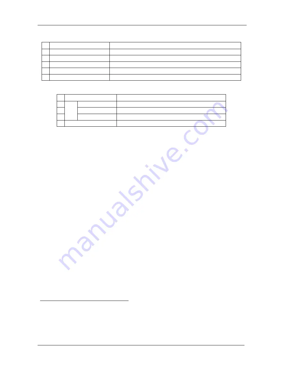
Table 1: Front and Rear Panel Features of the VP-12N 1:12 + 3 UXGA/CAT5 Distributor 

#  Feature 

Function 

POWER 

Switch 

Illuminated switch for turning the unit ON or OFF 

INPUT

 HD15F Connector 

Connect to the computer graphics (UXGA) source 

OUT

 HD15F Connectors 

Connect to the computer graphics (UXGA) acceptors (from 1 to 12) 

OUT

 RJ-45


Connectors 

Connect to

1

 the LINE IN RJ-45


connector

2

 (from 1 to 3) 

5  Power Connector with 

FUSE

  AC connector enabling power supply to the unit 

Table 2: Underside Features of the VP-12N 1:12 + 3 UXGA / CAT5 Distributor 

#  Feature 

Function 

BLUE 

Trimmer


Adjusts the blue level

3


GREEN 

Trimmer


Adjusts the green level

3


LE

V

E

L


RED 

Trimmer


Adjusts the red level

3


ID BIT

 CONTROL Switch


Slide to the left to set to ON

4

; to the right to set to OFF 

5  Using Your VP-12N 1:12 + 3 UXGA / CAT5 Distributor 

This section describes how to connect the 

VP-12N


1:12 + 3 UXGA / CAT5 

Distributor

The example in Figure 3 illustrates how to output a computer graphics signal 

from a computer to up to 12 local monitors, as well as how to transmit it over 

UTP cabling to 3 

TP-120


XGA Line Receiver 

units. 

To connect the 

VP-12N

 and up to 3 

TP-120


XGA Line Receiver 

units, do the 

following: 

1.  Connect a computer graphics source (for example, a computer) to the 

INPUT HD15F connector. 

2.  Connect the OUTPUT HD15F connectors to up to 12 acceptors (for 

example, Local Display 1 to Local Display 12). 

3.  Ensure that the ID BIT switch on the underside of the 

VP-12N

 is set to 

ON (by sliding it to the left). This would enable a notebook or laptop (if 

connected instead of a computer) to output a VGA signal to an external 

VGA monitor. 


1 Using a UTP cable with CAT5 connectors at both ends (the PINOUT is defined in Table 3 and Figure 4) 
2 For example, on the TP-120 XGA Line Receiver. Refer to the separate user manual: PT-110, WP-110, PT-120, TP-120, 
which can be downloaded from the Internet at this URL: http://www.kramerelectronics.com 
3 Insert a screwdriver into the small hole and carefully rotate it to adjust the level 
4 The default. Enabling the notebook or laptop to output a VGA signal to an external VGA monitor 

Содержание VP-12N

Страница 1: ...Kramer Electronics Ltd USER MANUAL Model VP 12N 1 12 3 UXGA CAT5 Distributor...

Страница 2: ...Figure 1 VP 12N 1 12 3 UXGA CAT5 Distributor 3 Figure 2 Underside of the VP 12N 1 12 3 UXGA CAT5 Distributor 3 Figure 3 Connecting the VP 12N 1 12 3 UXGA CAT5 Distributor 5 Figure 4 CAT5 PINOUT 6 Tab...

Страница 3: ...uge CAT5 cable Shielded Twisted Pair STP Unshielded Twisted Pair UTP The decision whether to use shielded twisted pair STP cable or unshielded twisted pair UTP cable depends on the nature of the appli...

Страница 4: ...Table 2 Underside Features of the VP 12N HD Version Feature Function 5 VS Switch Slide the switch to the left1 to change the VS polarity to negative polarity2 Slide the switch to the right to retain t...

Страница 5: ...at you Unpack the equipment carefully and save the original box and packaging materials for possible future shipment Review the contents of this user manual Use Kramer high performance high resolution...

Страница 6: ...ce Connect only good quality connection cables thus avoiding interference deterioration in signal quality due to poor matching and elevated noise levels often associated with low quality cables Avoid...

Страница 7: ...Your VP 12N 1 12 3 UXGA CAT5 Distributor 3 Figure 1 VP 12N 1 12 3 UXGA CAT5 Distributor Figure 2 Underside of the VP 12N 1 12 3 UXGA CAT5 Distributor...

Страница 8: ...example in Figure 3 illustrates how to output a computer graphics signal from a computer to up to 12 local monitors as well as how to transmit it over UTP cabling to 3 TP 120 XGA Line Receiver units T...

Страница 9: ...ector on a third TP 120 unit and connect the XGA OUT connector on that third TP 120 unit to Display 3 5 Connect the power cord3 not illustrated in Figure 3 6 Adjust4 the blue green and red signal leve...

Страница 10: ...e with RJ 45 connectors Table 3 CAT5 PINOUT EIA TIA 568A EIA TIA 568B PIN Wire Color PIN Wire Color 1 Green White 1 Orange White 2 Green 2 Orange 3 Orange White 3 Green White 4 Blue 4 Blue 5 Blue Whit...

Страница 11: ...MHz DIFF GAIN 0 17 at UXGA OUT DIFF PHASE 0 44 Deg at UXGA OUT K FACTOR 0 05 at UXGA and CAT5 OUT S N RATIO UXGA 73dB CAT5 70dB CONTROLS Level 0 8dB to 2 4dB COUPLING UXGA DC CAT5 AC POWER SOURCE 230...

Страница 12: ...s required the original dated invoice or a copy must be presented as proof of warranty coverage and should be included in any shipment of the product Please also include in any mailing a contact name...

Страница 13: ...or the latest information on our products and a list of Kramer distributors visit our Web site www kramerelectronics com where updates to this user manual may be found We welcome your questions commen...

Отзывы: