Kramer PIP-400 Скачать руководство пользователя страница 12

Installing on a Rack 


9

5  Installing on a Rack 

This section describes what to do before installing on a rack and how to rack 

mount. 

Before installing on a rack, be sure that the environment is 

within the recommended range:

Operating temperature range +5 to +45 Deg. Centigrade

5 to 65% RHL, non-condensing

-20 to +70 Deg. Centigrade
5 to 95% RHL, non-condensing

Operating humidity range
Storage temperature range
Storage humidity range

When installing on a 19" rack, avoid hazards by taking 

care that:

It is located within the recommended environmental 

conditions, as the operating ambient temperature of a 

closed or multi unit rack assembly may exceed the 

room ambient temperature.

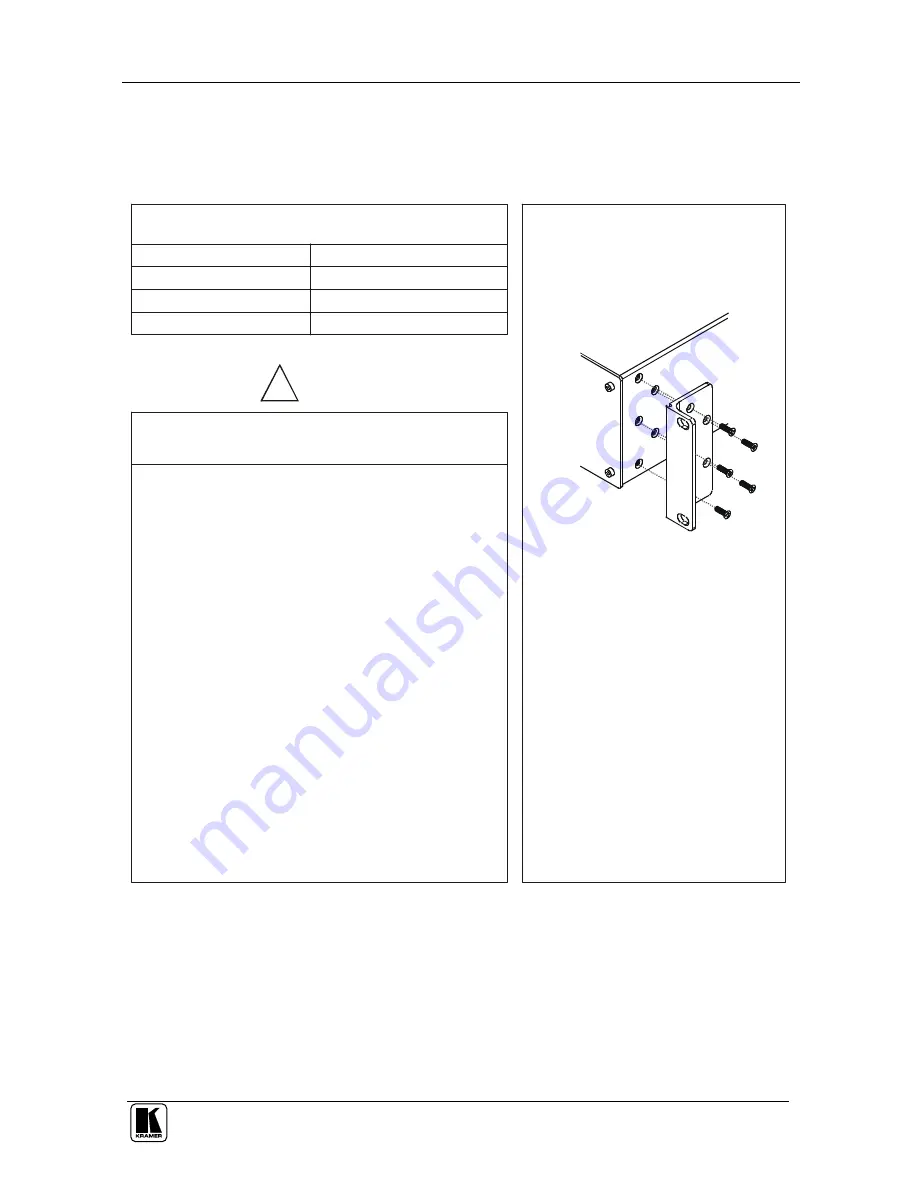
Attach both ear brackets to the 

machine. To do so, remove the 

screws from each side of the machine 

(5 on each side), and replace those 

screws through the ear brackets.

Place the ears of the machine 

against the rack rails, and insert the 

proper screws (not provided) through 

each of the four holes in the rack 

ears

.

 Note that:

Detachable rack ears can be removed 

for desktop use
Always mount the machine in the rack 

before you attach any cables or 

connect the machine to the power 
If you are using a Kramer rack adapter 

kit (for a machine that is not 19"), see 

the Rack Adapters user manual for 

installation instructions (you can 

download it at: 

http://www.kramerelectronics.com)

In some models, the front panel 

may feature built-in rack ears

Once rack mounted, enough air will still flow around the 

machine.
The machine is placed straight in the correct horizontal 

position.

You do not overload the circuit(s). When connecting 

the machine to the supply circuit, overloading the 

circuits might have a detrimental effect on overcurrent 

protection and supply wiring. Refer to the appropriate 

nameplate ratings for information. For example, for 

fuse replacement, see the value printed on the product 

label.

The machine is earthed (grounded) in a reliable way 

and is connected only to an electricity socket with 

grounding. Pay particular attention to supply 

connections other than direct connections to the 

branch circuit (for example, the use of power strips), 

and that you use only the power cord that is supplied 

with the machine.

CAUTION!!

Before Installing on a Rack

How to Rack Mount

To rack-mount a machine:

1

1

2

2

3

4

5


Содержание PIP-400

Страница 1: ...Kramer Electronics Ltd USER MANUAL Models PIP 400 Picture in Picture Inserter Quad Split PIP 500 Picture in Picture Inserter Quad Split...

Страница 2: ...rs in the PIP Mode 18 7 2 1 Selecting a Different Channel as the Background 19 8 Firmware Upgrade 20 8 1 Downloading from the Internet 20 8 2 Connecting the PC to the RS 232 Port 20 8 3 Upgrading Firm...

Страница 3: ...P 500 Main Menu Items 13 Table 4 The MODE Submenu Features 15 Table 5 PIP Sizing and Positioning Features 16 Table 6 Recommended PIP sizes 16 Table 7 Video Settings Submenu Features 16 Table 8 Presets...

Страница 4: ...cord and Null modem adapter for control via RS 232 This user manual2 2 Getting Started We recommend that you Unpack the equipment carefully and save the original box and packaging materials for possib...

Страница 5: ...INGS INPUT SELECT OUTPUT STANDARD PRESETS INPUTS 5 4 3 2 1 ENTER LAYE R FR EEZE ES C CV Y C QUAD OUT Y CV B Y R Y Y C OUTPUT Y CV B Y R Y Y C Y Y CV CV CV B Y B Y B Y R Y Y CV B Y R Y R Y Y C Y R Y Y...

Страница 6: ...sing the PIP 400 PIP 500 you can do the following Position sources on the screen as desired and select their size from a list Put a text label in each inserted picture Put a border around each inserte...

Страница 7: ...y cables Avoid interference from neighboring electrical appliances and position your Kramer PIP 400 PIP 500 away from moisture excessive sunlight and dust 4 Your Picture in Picture Inserter Quad Split...

Страница 8: ...5 INPUTS 4 3 2 1 ENTER LAYER FREEZE ESC Y Y CV CV CV CV B Y B Y B Y R Y Y CV B Y R Y R Y Y C Y R Y Y C Y C Y CV B Y R Y Y C Y C RELAY RS 232 Y C INPUT 4 INPUT 1 INPUT 3 OUTPUT INPUT 2 QUAD OUT FUSE Fi...

Страница 9: ...es 6 INPUTS 5 4 3 2 1 ENTER LAYER FREEZE ESC Y Y Y CV CV CV CV CV B Y B Y B Y B Y R Y Y CV B Y R Y R Y R Y Y C Y R Y Y C Y C Y CV B Y R Y Y C Y C RELAY RS 232 Y C INPUT 4 INPUT 1 INPUT 3 OUTPUT INPUT...

Страница 10: ...e Labeling menu 5 7 Moves the selected image upwards in the PIP mode4 Moves up one step in the same level in the OSD screen Increases the range by one step in the OSD screen Use to change the selected...

Страница 11: ...20 R Y BNC Connector Connects to the component 2 video acceptor 21 OUTPUT Y C 4p Connector Connects to the s Video acceptor 22 PROG IN Push in to upgrade to the latest Kramer Firmware see section 8 23...

Страница 12: ...ktop use Always mount the machine in the rack before you attach any cables or connect the machine to the power If you are using a Kramer rack adapter kit for a machine that is not 19 see the Rack Adap...

Страница 13: ...for example a composite video display The Y C OUTPUT 4p connector to the s Video acceptor for example an s Video display The Y B Y and R Y OUTPUT BNC connectors to the component video acceptor for exa...

Страница 14: ...deo Player 1 Composite Video Display Component Video Projector Composite Video Quad Display s Video Quad Display s Video Display Composite Video Player 3 Composite Video Player 5 Composite Video Playe...

Страница 15: ...dapter with a 9 wire flat cable to the RS 232 DB9 port on your PC To connect a PC to the PIP 500 unit without using a Null modem adapter Connect the RS 232 DB9 port on your PC to the RS 232 DB9 rear p...

Страница 16: ...illustrates the PIP menu guide Table 3 The PIP 500 Main Menu Items Menu Item Function MODE Select between the SINGLE PIP and QUAD modes see section 7 1 1 OSD Activates deactivates the OSD menu 4 BORDE...

Страница 17: ...ESET 2 START VIDEO SETTINGS PRESETS LABELING OSD BORDER INPUT SELECT MODE PIP 1 4 PIP POSITION SINGLE 1 1 PIP SIZING QUAD 1 9 ON WHITE CONTRAST COMPOSITE STORE OFF USE ARROWS TO MOVE OFF COLOUR BRIGHT...

Страница 18: ...n the screen Once the PIP mode is selected the PIP SIZING and PIP POSITION commands appear as illustrated in Figure 6 see section 7 1 1 1 The LCD display shows PIP Mode QUAD 2 Displays 4 quarter sized...

Страница 19: ...windows according to Table 6 Combinations having window sizes larger than recommended may result in intermittent interruptions in the picture Note that these restrictions only apply when a 1 1 sized...

Страница 20: ...nking Use the and buttons to select the first desired letter5 Use the button to continue to the next letter Use the button to return to the previous letter Use the ENTER button to accept changes For e...

Страница 21: ...ntinue to the next letter 8 Press the or buttons to change the remaining characters to blank spaces 9 Press ENTER to accept changes 7 2 Displaying the Layers in the PIP Mode To display a picture in pi...

Страница 22: ...P sizing 1 9 Channel 4 in front PIP sizing 1 16 B Select Channel 4 and size it to 1 1 as follows A Press INPUT 4 B Press the LAYER button or follow steps 1 to 3 1 Press ENTER 2 Press ENTER again to se...

Страница 23: ...he EXE file and install the GOAL TENDER programmer software following the on screen installation instructions 8 2 Connecting the PC to the RS 232 Port Before installing the latest Kramer firmware vers...

Страница 24: ...START button The software erases and then programs flash memory Upon completion of the operation the System Status Window displays Erase and program completed successfully see Figure 9 Figure 9 Syste...

Страница 25: ...p 75 on a 4p connector 1 composite video 1Vpp 75 on a BNC connector QUAD OUTPUTS 1 s Video 1Vpp 0 3Vpp 75 on a 4p connector 1 composite video 1Vpp 75 on a BNC connector DIGITAL RESOLUTION 10 bit VIDEO...

Страница 26: ...TE34 BYTE33 BYTE32 BYTE31 BYTE30 3rd byte LAST 1 BYTE37 0 0 1 0 0 0 4th byte 1st BYTE Bit 7 Defined as 0 Bit 6 DESTINATION BIT 0 information is sent from the PC to the PIP 1 information is sent from t...

Страница 27: ...nput number 0 to maximum to the right 0x1c PIP position Y 1 to 5 input number 0 to maximum to the bottom 0x1d Border 0 0 Off 1 White border 2 Black border 0x1e Freeze 1 to 5 input number 0 Normal oper...

Страница 28: ...ith will recall the settings stored in non volatile memory Byte2 selects the memory address 1 or 2 To recall the factory reset settings select byte2 0 There is no inquire RQ for this instruction For e...

Страница 29: ...o 1 9 send 0x1a 0x82 0x83 0x88 To find out the PIP size of input 2 in this case send 0x1a 0xc2 0x80 0x88 The unit responds by sending 0x5a 0xc2 0x83 0x88 Instruction 0x1b PIP position X Sending this i...

Страница 30: ...independent of the OSD status To inquire if the OSD is on set the RQ bit The unit responds by setting Byte3 appropriately For example To turn on the OSD send 0x31 0x80 0x81 0x88 To inquire about the...

Страница 31: ...is required the original dated invoice or a copy must be presented as proof of warranty coverage and should be included in any shipment of the product Please also include in any mailing a contact name...

Страница 32: ...or the latest information on our products and a list of Kramer distributors visit our Web site www kramerelectronics com where updates to this user manual may be found We welcome your questions commen...

Отзывы: