


3 Technical data
3.4 Connection field
3.4 Connection field
1
2
3
4
5
6
7
8
9
0
0
0
7
6
6
1
2
3
4
5
6
7
8
9
1
0
1
1
1
2
1
3
1
4
1
5
1
6
1
7
1
8
1
9
2
0
2
1
A+
B-
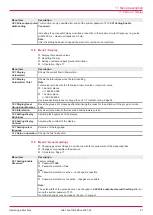
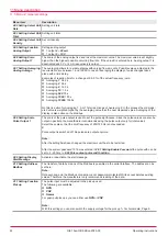
Fig. 2: Termination panel electronic unit
1
Power supply (24 V DC)
6
Pick up 1
2
Analog output (4 - 20 mA)
7
Pick up 2
3
Analog output (0 – 10 V)
8
Analog input (0 – 10 V)background illumination
4
Serial interface (RS 232)
9
Pulse output
5
Modbus interface (RS 485)
The Modbus connection takes place via terminals. The assignment of the terminals is shown in the wir-
ing diagram. The address of the electronic unit at the Modbus can be selected per software, see
2.10
Modbus address
.
3.5 Pin assignment
Component
Connection/function
Terminal
Pick up
NPN/PNP
Push-pull
Namur
Pick up 1
U+24 V DC
U+8.2 V DC
12
Signal
Signal
13
Gnd
–
14
Pick up 2 (+90°)
U+24 V DC
U+8.2 V DC
15
Signal
Signal
16
Gnd
–
17
Operating instructions
OIE 15en-GB Edition 2020-03
7