


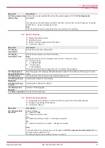

14 Troubleshooting
14.1 Fault table
Fault display
Cause and elimination
7.15 Alarm 14
Temperature range
electronics exceeded.
The temperature range of the electronic unit has been exceeded.
o
Check the electronic unit.
o
Replace the electronic unit.
7.16 Alarm 15 Unit
density changed.
Correct the density
table!
The unit of density has been changed.
o
Convert the numerical value and correct the density value.
7.18 Alarm 17 Unit
changed Correct the
scale of analog output!
The unit of the rate has been changed.
o
Check the scale of the analog outputs and correct it.
7.19 Alarm 18 Unit
changed Correct the
scale of pulse output!
The unit of Total has been changed.
o
Check the scale of the pulse outputs and correct it.
Further faults
Further faults
Cause and elimination
Rate = 0, although pulse
signals can be measured
at the terminals of the
electronic unit with the
oscilloscope.
One pick up each is connected and the function Pulse input
Encoder
selected.
o
2.13 Setting Function Pulse Inputs
Set to
Counter
.
Analog output does not
function.
Analog output function selected incorrectly.
o
Select the correct function, see
2.05 Setting Function Analog Output
Signal cable connected to an incorrect analog output.
o
Correct the connection.
Negative flow
The signal wires at the respective flowmeter are connected incorrectly.
o
Swap the signal wires.
No flow or flow rate too
low
o
Check the alarms, see
Menu 7 Alarms
o
Check the connection of the pick up.
o
Check the pick up and replace it if necessary.
Double flow when the op-
tion flow direction detec-
tion is used
o
Switch the function of the pulse input from
Counter
to
Encoder
, see
2.13 Setting Function
Pulse Inputs
.
When the electronic unit
is switched on, the fol-
lowing alarms are dis-
played:
o
7.07 Alarm 6
Maximum flow is
exceeded. Check
volumeter!
o
7.09 Alarm 8 Analog
output scaling max
exceeded.
o
7.11 Alarm 10
Sensor failure pick
up volumeter A.
o
Use a power pack 24 V DC 15 W or insert a debounced switch between the electronic unit and
power pack
o
Shield the lines to the pick ups and terminate the shield to Gnd (chassis) or ground.
Keyboard background il-
lumination flashes.
There is an input error.
o
Press +
simultaneously.
-> The existing errors are displayed.
o
Eliminate errors.
Operating instructions
OIE 15en-GB Edition 2020-03
25