12
IT
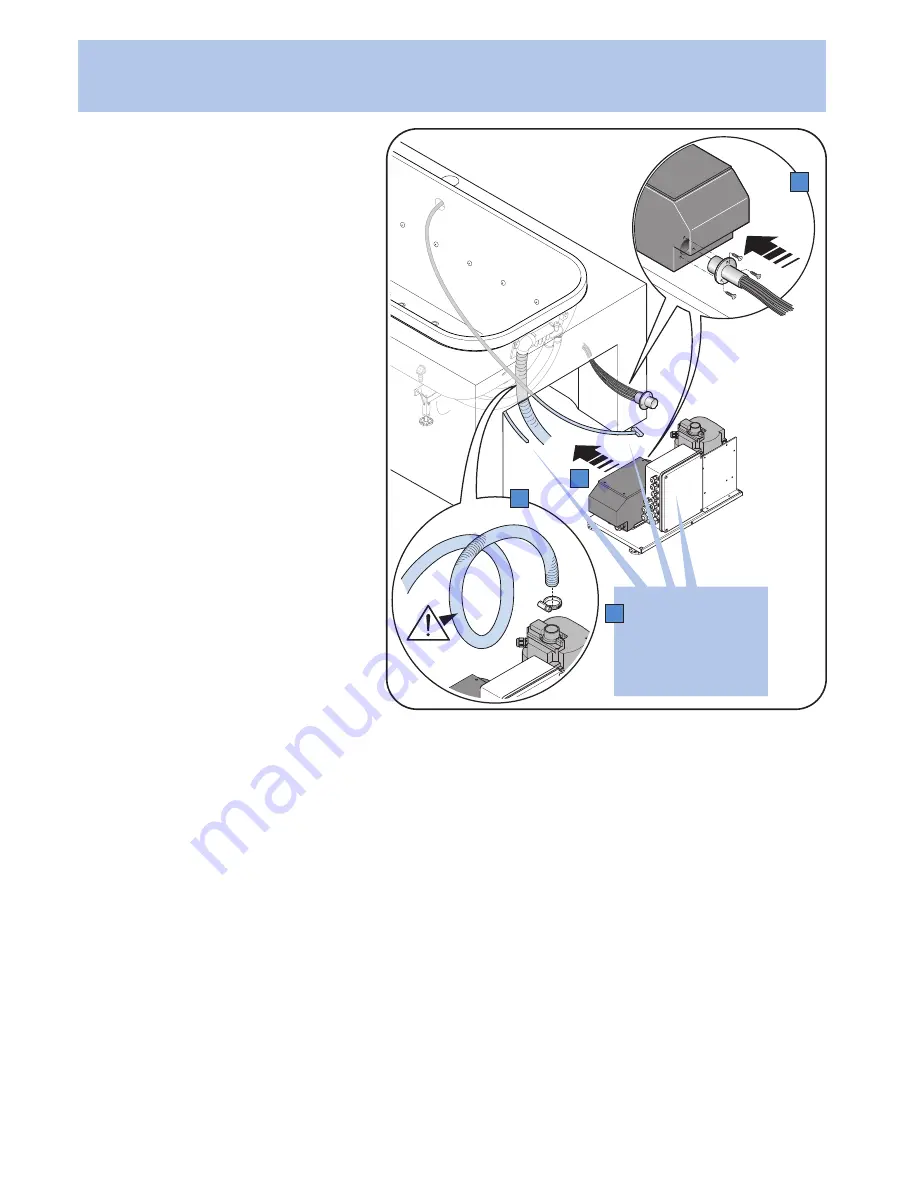
fig.5)
A)
Collegare il tubo blower, avendo cura di realizzare una
spirale (vedi figura), per evitare il reflusso dell’acqua.
B)
Collegare le fibre ottiche (solo modd. con IDROCOLORE
- per maggiori dettagli consultare il cap. dedicato)
C)
Effettuare tutti i collegamenti elettrici.
Allacciamento elettrico (vedi schemi elettrici)
La vasca è dotata di una morsettiera alla quale va collegato il cavo
di alimentazione che deve essere del tipo: H05VV-F tripolare con
sezione 2,5 mm
2
(3x2,5).
Dopo aver fatto passare il cavo attraverso l‘apposito pressacavo
collegare il conduttore blu (neutro) al morsetto N, quello marrone
(fase) al morsetto L e quello giallo - verde al morsetto terra. Serrare
il pressacavo e collocare in posizione il coperchio della control
box per garantire il grado di protezione prescritto.
La vasca è anche dotata di un morsetto contrassegnato con il
simbolo equipotenziale predisposto per accogliere un conduttore
di sezione compresa tra 2,5 e 6 mm
2
. Utilizzare il detto morsetto
per collegare la vasca all‘impianto di messa ad equipotenziale
delle masse metalliche dell‘immobile.
Prova di funzionamento
- Pulire accuratamente l‘interno della vasca.
- Dare tensione al circuito elettronico per mezzo dell‘interruttore
generale.
- Riempire d‘acqua la vasca fino a coprire le bocchette.
Vedi capitolo relativo del “MANUALE D‘USO E MANUTENZIO-
NE”.
- Avviare l‘idromassaggio e tenerlo in funzione per almeno un
ciclo (15 minuti).
- Verificare che non ci siano perdite sui circuiti idraulici.
- Avviare anche le altre funzioni della vasca (Blower - Idrocolore®)
e verificare il buon funzionamento.
- Alla fine del test svuotare la vasca.
Si raccomanda di prestare la massima attenzione al raccordo
dello scarico.
GB
fig.5)
A)
Connect the blower tube. Make sure you create a spiral
(see figure) to prevent the backflow of water.
B)
Connect the optic fibres (only models with IDROCOLORE
- for further information, refer to the dedicated chapter)
C)
Make all electrical connections.
Place the tub as close as possible to its installation area and go
ahead with the related electrical and plumbing connections.
Electrical connections (see electrical diagrams)
The tub is fitted with a terminal board to which the power supply cord should
be connected.
The power supply cord should be three-pole H05VV-F with a 2.5 mm
2
section
(3x2.5).
After passing the cord through the special cord grip, connect the blue wire
(neutral) to terminal N, the brown wire (live) to terminal L and the yellow and
green wire to the earth terminal.
Tighten the cord grip and place the control box cover in position to ensure the
prescribed degree of protection.
The tub is also fitted with a terminal marked with the potential compensation
symbol, designed to take a cable with a section of between 2.5 and 6 mm
2
.
Use this terminal to connect the tub to the building’s potential compensation
system.
Testing procedure
- Clean the interior of the tub thoroughly.
- Supply voltage to the electronic circuit by switching the main switch on.
- Fill the tub with enough water to cover the jets.
- See the appropriate chapter in the “USE AND MAINTENANCE MANUAL”.
- Switch on the whirlpool tub and keep it running for at least one cycle (15
minutes).
- Check that there are no leaks in the plumbing circuits.
- Switch on the other tub functions (Blower - Idrocolore®) and check that they
are working correctly.
Fig.
Abb.
5
C
D
B
A
- Empty the tub at the end of the test.
It is recommended that extreme care should be taken when checking the
drainage outlet.
FR
fig.5)
A)
Raccorder le tube blower, en prenant soin de réaliser une spirale (voir
figure), afin d’éviter le reflux de l’eau
B)
Raccorder les fibres optiques (uniquement mod. avec IDROCOLORE -
pour plus de détails consulter le chap. dédié)
C)
Effectuer tous les branchements électriques.
Branchement électrique (voir schémas électriques)
La baignoire est munie d’une barrette de connexion à laquelle doit être connecté
le câble d’alimentation qui doit être du type: H05VV-F tripolaire avec une section
de 2,5 mm
2
(3x2,5). Après avoir fait passer le câble dans le serre-câble prévu à
cet effet, connecter le conducteur bleu (neutre) à la borne N, le conducteur brun
(phase) à la borne L et le con-ducteur jaune-vert à la borne de terre. Serrer le
serre-câble et remettre en place le couver-cle du coffret pour garantir le degré
de protection prescrit. La baignoire est munie également d’une borne identifiée
par le symbole de terre prévue pour accueillir un conducteur d’une section
comprise entre 2,5 et 6 mm
2
.
Utiliser cette borne pour raccorder la baignoire à l’installation de mise à la terre
des masses métalliques de l’édifice.
Essai de fonctionnement
- Nettoyer soigneusement l’intérieur de la baignoire.
- Alimenter le circuit électronique au moyen de l’interrupteur général.
- Remplir d’eau la baignoire de manière à couvrir les buses. Voir chapitre
correspondant dans le “MANUEL D’INSTRUCTIONS POUR L’EMPLOI ET L’EN-
IT - ALLACCIAMENTI
GB - CONNECTIONS
DE - ANSCHLÜSSE
FR - RACCORDEMENTS
ES - CONEXIONES
PT - LIGAÇÕES
Vedere schemi elettrici
See electrical diagrams
Voir schémas électriques
Siehe elektrische Schaltpläne
Vea los esquemas eléctricos
Ver os esquemas eléctricos


