9
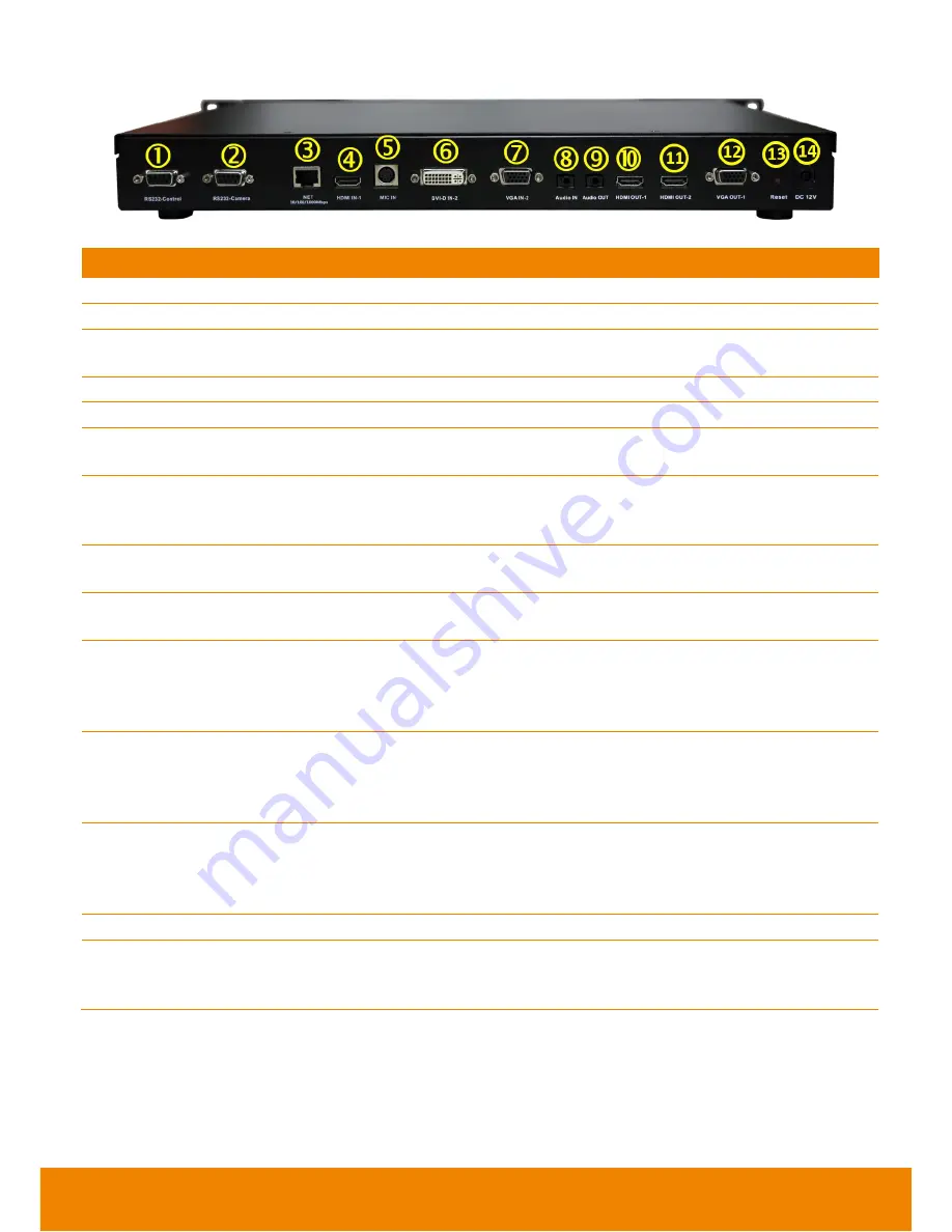
Back Panel:
Name
Function
(1) RS232-CONTROL
For system control.
(2) RS232-CAMEAR
For Camera Control
(3) LAN Port
Use the RJ-45 Ethernet cable to connect an IP-based network to the LAN
port.
(4) HDMI IN-1
To connect a camera
(5) MIC IN
Receive audio signal from MIC device via a mini din 8 pin MIC cable.
(6) DVI-D IN-2
Using the DVI to HDMI connector to transfer the DVI to HDMI interface and
through the HDMI cable connects to the PC or NB.
(7) VGA IN-2
Connect the VGA cable to the VGA input port located on the back panel,
and connect the other end of VGA cable to a VGA input source (ex.
Document camera, Laptop or Desktop) to input video signal.
(8) AUDIO IN
Receive audio signal from an external audio source through the audio
cable.
(9) AUDIO OUT
Use to connect the main system to external speakers or amplifiers for
audio signal output.
(10) HDMI OUT-1
Connect an HDMI cable from the HDMI monitor to HDMI OUT-1. The
HDMI interface allows you to transmit both audio and video signals over a
single cable (HDMI cable). In dual display mode, the output screen
connected to this port will be set up to primary screen automatically.
(11) HDMI OUT-2
Connect the HDMI cable to the HDMI OUT-2 to connect the other end of
HDMI cable to a display device to output both video and audio signal. In
dual display mode, the output screen connected to this port will be set up
to secondary screen automatically.
(12) VGA OUT-1
Connect the VGA cable to the VGA output port located on the back panel,
and connect the other end of VGA cable to a display device to output video
signal. In dual display mode, the output screen connected to this port will
be set up to primary screen automatically.
(13) RESET Button
Press it to reboot the main system unit.
(14) POWER
Connect the power supply cord and adapter to the power port located on
the back panel. And connect the other end of the power cord to a suitable
power outlet.


