CP3002-RC/CP3002-RA
Configuration
ID 1039-3625, Rev. 1.0
Page 4 - 7
P R E L I M I N A R Y
4.3.3
Control Register 0 (CTRL0)
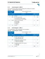
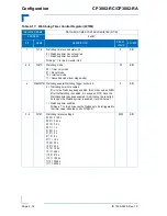
The Control Register 0 holds one bit for specifying the boot Flash to be updated.
4.3.4
Control Register 1 (CTRL1)
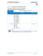
The Control Register 1 holds board-specific control information.
Table 4-8:
Control Register 0 (CTRL0)
REGISTER NAME
CONTROL REGISTER 0 (CTRL0)
ADDRESS
0x282
BIT
NAME
DESCRIPTION
RESET
VALUE
ACCESS
7 - 6
Res.
Reserved
00
R
5
BFUS
Boot Flash update selection:
0 = Select default boot Flash for update
1 = Select alternative boot Flash for update
0
R/W
3 - 2
CPMC2
COMB port mode configuration:
00 = RS-232 mode
01 = RS-422 mode
10 = Reserved
11 = Reserved
01
R/W
1 - 0
Res.
Reserved
00
R
Table 4-9:
Control Register 1 (CTRL1)
REGISTER NAME
CONTROL REGISTER 1 (CTRL1)
ADDRESS
0x283
BIT
NAME
DESCRIPTION
RESET
VALUE
ACCESS
7
SRST
SATA Flash module configuration:
0 = Reset of SATA Flash module
1 = SATA Flash module running
1
R/W
6
VRST
Integrated graphics controller configuration:
0 = Graphics controller disabled
1 = Graphics controller enabled
1
R
5
TRST
Trusted Platform Module (TPM) configuration:
0 = TPM disabled
1 = TPM enabled
1
R/W
4 - 0
Res.
Reserved
00000
R


