background image

COMe-cBT6 / User Guide


52


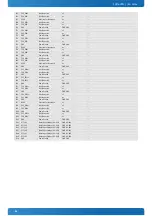
B58 

PCI Express Lane 3 R 

DP-I 

only available on no-LAN var. 

B59 

PCIE_RX3- 

PCI Express Lane 3 Receive - 

DP-I 

only available on no-LAN var. 

B60 

GND 

Power Ground 

PWR GND 

B61 

PCI Express Lane 2 R 

DP-I 

B62 

PCIE_RX2- 

PCI Express Lane 2 Receive - 

DP-I 

B63 

GPO3 

General Purpose Output 3 

O-3.3 

PD 100k 

B64 

PCI Express Lane 1 R 

DP-I 

B65 

PCIE_RX1- 

PCI Express Lane 1 Receive - 

DP-I 

B66 

WAKE0# 

PCI Express Wake Event 

I-3.3 

PU 10k 3.3V (S5) 

B67 

WAKE1# 

General Purpose Wake Event 

I-3.3 

PU 10k 3.3V (S5) 

B68 

PCI Express Lane 0 R 

DP-I 

B69 

PCIE_RX0- 

PCI Express Lane 0 Receive - 

DP-I 

B70 

GND 

Power Ground 

PWR GND 

B71 


LVDS Channel B DAT0+ 

DP-O 

B72 

LVDS_B0- 

LVDS Channel B DAT0- 

DP-O 

B73 


LVDS Channel B DAT1+ 

DP-O 

B74 

LVDS_B1- 

LVDS Channel B DAT1- 

DP-O 

B75 


LVDS Channel B DAT2+ 

DP-O 

B76 

LVDS_B2- 

LVDS Channel B DAT2- 

DP-O 

B77 


LVDS Channel B DAT3+ 

DP-O 

B78 

LVDS_B3- 

LVDS Channel B DAT3- 

DP-O 

B79 

LVDS_BKLT_EN 

Panel Backlight On 

O-3.3 

PD 100k 

B80 

GND 

Power Ground 

PWR GND 

B81 

LV 

LVDS Channel B Clock+ 

DP-O 

B82 

LVDS_B_CK- 

LVDS Channel B Clock- 

DP-O 

B83 

LVDS_BKLT_CTRL  Backlight Brightness Control 

O-3.3 

B84 

VCC_5V_SBY 

5V Standby 

PWR 5V (S5) 

optional (not neccessary in single supply mode) 

B85 

VCC_5V_SBY 

5V Standby 

PWR 5V (S5) 

optional (not neccessary in single supply mode) 

B86 

VCC_5V_SBY 

5V Standby 

PWR 5V (S5) 

optional (not neccessary in single supply mode) 

B87 

VCC_5V_SBY 

5V Standby 

PWR 5V (S5) 

optional (not neccessary in single supply mode) 

B88 

BIOS_DIS1# 

BIOS Selection Strap 1 

I-3.3 

PU 10k 3.3V (SPI) 

PU might be powered during suspend 

B89 

CRT_RED 

CRT_RED / Analog Video RGB-RED 

OA 

PD 150R 

B90 

GND 

Power Ground 

PWR GND 

B91 

CRT_GREEN 

CRT_GREEN / Analog Video RGB-GREEN 

OA 

PD 150R 

B92 

CRT_BLUE 

CRT_BLUE / Analog Video RGB-BLUE 

OA 

PD 150R 

B93 

CRT_HSYNC 

CRT_HSYNC / Analog Video H-Sync 

O-3.3 

B94 

CRT_VSYNC 

CRT_VSYNC / Analog Video V-Sync 

O-3.3 

B95 

CRT_DDC_CLK 

CRT_DDC_CLK / Display Data Channel Clock 

I/O-5 

PU 2k21 5.0V_S0 

B96 

CRT_DDC_DATA 

CRT_DDC_DATA / Display Data Channel Data 

I/O-5 

PU 2k21 5.0V_S0 

B97 

SPI_CS# 

SPI Chip Select 

O-3.3 

B98 

RSVD 

Reserved for future use 

nc 

B99 

RSVD 

Reserved for future use 

nc 

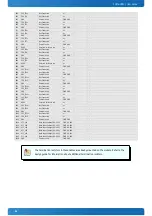
B100  GND 

Power Ground 

PWR GND 

B101  FAN_PWMOUT 

Fan PWM Output 

O-3.3 

20V protection circuit implemented on module, PD on 
carrier board needed for proper operation 

B102  FAN_TACHIN 

Fan Tach Input 

I-3.3 

PU 47k 3.3V (S0) 

20V protection circuit implemented on module 

B103  SLEEP# 

Sleep Button Input 

I-3.3 

PU 47k 3.3V (S5) 

20V protection circuit implemented on module 

B104  VCC_12V 

Main Input Voltage (8.5-20V) 

PWR 8.5-20V  - 

B105  VCC_12V 

Main Input Voltage (8.5-20V) 

PWR 8.5-20V  - 

B106  VCC_12V 

Main Input Voltage (8.5-20V) 

PWR 8.5-20V  - 

B107  VCC_12V 

Main Input Voltage (8.5-20V) 

PWR 8.5-20V  - 

B108  VCC_12V 

Main Input Voltage (8.5-20V) 

PWR 8.5-20V  - 

B109  VCC_12V 

Main Input Voltage (8.5-20V) 

PWR 8.5-20V  - 

B110  GND 

Power Ground 

PWR GND 

Содержание COMe-cBT6

Страница 1: ...www kontron com COMe cBT6 User Guide COMe cBT6 User Guide Doc Rev 2 0...

Страница 2: ...www kontron com COMe cBT6 User Guide This page has been intentionally left blank...

Страница 3: ...the specified use without further testing or modification Kontron expressly informs the user that this user guide only contains a general description of processes and instructions which may not be app...

Страница 4: ...your risk To minimize the risks associated with your products and applications you should provide adequate design and operating safeguards You are solely responsible for compliance with all legal regu...

Страница 5: ...ort Find Kontron contacts by visiting http www kontron com support Customer Service As a trusted technology innovator and global solutions provider Kontron extends its embedded market strengths into a...

Страница 6: ...Functionality 9 2 4 COM Express Documentation 10 2 5 COM Express Benefits 10 3 Product Specification 11 3 1 Modules Definition 11 3 2 FunctionalSpecification 12 3 3 Block Diagram 16 3 4 Accessories 17...

Страница 7: ...al Peripheral Interface SPI 33 4 6 SPI boot 33 4 7 M A R S 35 4 8 UART 36 4 9 Fast I2C 37 4 10 Dual Staged Watchdog Timer 38 4 11 SpeedstepTechnology 39 4 12 C States 40 4 13 Graphics Features 41 4 14...

Страница 8: ...BIOS Operation 57 7 1 Determining the BIOS Version 57 7 2 BIOS Update 57 7 3 POST Codes 58 7 4 Setup Guide 58 7 5 BIOS Setup 59 7 5 1 Main 59 7 5 2 Advanced 64 7 5 3 Security 87 7 5 4 Boot 88 7 5 5 E...

Страница 9: ...ights reserved No part of this document may be reproduced transmitted transcribed stored in a retrieval system or translated into any language or computer language in any form or by any means electron...

Страница 10: ...mini form factor 55mm x 84mm The product names for Kontron COM Express Computer on Modules consist of a short form of the industry standard COMe the form factor b basic c compact m mini the capital l...

Страница 11: ...OM Express modules The baseboard designer can optimize exactly how each of these functions implements physically Designers can place connectors precisely where needed for the application on a baseboar...

Страница 12: ...SODIMM YES Intel i210IT 8x Commercial temperature grade modules 0 C to 60 C operating Part Number Product Name Processor Memory eMMC TPM mSD Socket Ethernet USB 2 0 36017 0000 20 4 COMe cBTc6 J1900 I...

Страница 13: ...Thermal Design Power TDP 10W 8W 7W 6W 5W 3W 10W 7 5W 4 3W SDP 4 5W 2 5W C States C1 C1E C6 C1 C1E C6 C1 C1E C6 C1 C1E C6 C1 C1E C6 C1 C1E C6 C1 C1E C6 C1 C1E C6 C7 C1 C1E C6 C7 Smart Cache 2x1MB 2x512...

Страница 14: ...x18 24 with DP2LVDS LVDS Bits Pixel with dithering LVDS max Resolution 1920x1200 PWM Backlight Control YES Supported Panel Data EDID DID Display Interfaces Discrete Graphics Digital Display Interface...

Страница 15: ...1 Port 2 Port 3 Default x1 x1 x1 LAN Configuration 1 x2 x1 x1 Configuration 2 x1 x1 x1 x1 Configuration 3 x2 x1 x1 Configuration 4 x2 x2 Configuration 5 x4 Ethernet The Intel i210IT i211AT ethernet su...

Страница 16: ...y Power Features Singly Supply Support YES Supply Voltage 4 75 20V ACPI ACPI 3 0 S States S0 S3 S4 S5 S5 Eco Mode YES Misc Power Management DPST 4 0 iFFS Power Consumption and Performance Full Load Po...

Страница 17: ...02 BIO S LPC2I2C GPIO Buffer Watchdog UART Power sequencing D P Intel Atom E3800 Intel Celeron J1900 N29xx N28xx FAN1 GB LAN Embedded Controller CPLD EPM1270 HWM I2C LID PwrCtrl GPIO SER0 Sleep SysMgm...

Страница 18: ...or 1 module including screws for 8mm connectors 38017 0100 00 0 COMe Mount Kit 8mm 100sets Mounting Kit for 100 modules including screws for 8mm connectors Part Number Cooling Solutions Comment 36099...

Страница 19: ...ltage from 10 to 90 of its final set point following the ATX specification 3 5 3 Supply Voltage Ripple Maximum 100 mV peak to peak 0 20 MHz 3 5 4 Power Consumption The maximum Power Consumption of the...

Страница 20: ...V VCC S0 high high 5V low VCC 3 5 6 Single Supply Mode In single supply mode or automatic power on after power loss without 5V Standby the module will start automatically when VCC power is connected...

Страница 21: ...ignal Pin B24 The implementation of this subsystem complies with the COM Express Specification PWR_OK is internally pulled up to 3 3V and must be high level to power on the module 3 6 4 Reset Button S...

Страница 22: ...temperature with ambient being the air surrounding the module the maximum measurable temperature on any spot on the heatspreader s surface Test specification Temperature Grade Validation requirements...

Страница 23: ...orm factor Computer on Modules are Recognized by Underwriters Laboratories Inc Representative samples of this component have been evaluated by UL and meet applicable UL requirements UL Listings NWGQ2...

Страница 24: ...ock and vibration tests according to IEC EN 60068 2 6 Non operating Vibration sinusoidal 10Hz 4000Hz 0 15mm 2g IEC EN 60068 2 27 Non operating Shock Test half sinusoidal 11ms 15g EMC Validated in Kont...

Страница 25: ...e only battery drain is from leakage paths 3 9 MTBF The following MTBF Mean Time Before Failure values were calculated using a combination of manufacturer s test data if the data was available and the...

Страница 26: ...of 13mm from bottom to heatspreader top Cooling solutions provided from Kontron for compact sized Computer on Modules are 27mm in height from module bottom to Heatsink top Universal Cooling solutions...

Страница 27: ...COMe cBT6 Introduction 25 3 11 Module Dimensions All...

Страница 28: ...ication Part number Molex J3 53261 0371 Mates with 51021 0300 Crimp terminals 50079 8100 Pin assignment Pin1 Tacho Pin2 VCC Pin3 GND Electrical characteristic Module Input Voltage 4 75 13V 13 FAN Outp...

Страница 29: ...modules E2 XT The aluminum slugs and thermal pads or the heat pipe on the underside of the heatspreader assembly implement thermal interfaces between the heatspreader plate and the major heat generati...

Страница 30: ...ll SLC technology Industrial temperature grade 45 to 85 C Flash Part No KE4CN2H5C xxx KE4CN3H5C xxx KE4CN4K6C xxx KE4CN5B6C xxx KE4CN6C6C xxx Nominal Flash Size MLC 4GByte 8GByte 16GByte 32GByte 64GBy...

Страница 31: ...100 xxx Nominal Flash Size MLC 4GByte 8GByte 16GByte 32GByte 64GByte Nominal Flash Size SLC 2GByte 4GByte 8GByte 16GByte 32GByte JEDEC Standard eMMC 4 5 eMMC 4 5 eMMC 4 5 eMMC 4 5 eMMC 5 0 Flash Techn...

Страница 32: ...n 2 0 Wear Leveling and ECC High reliability MTBF 2 000 000 hours 2 000 000 write erase cycles Industrial Temperature range up to 17MB s data transfer speed Order information Density Manufacturerer Pa...

Страница 33: ...ually up to 300mA just to stay off This mode allows to be switched on by power button RTC event and WakeOnLan even when it is not necessary The new S5 Eco mode reduces the current enormous The S5 Eco...

Страница 34: ...than one device is used on LPC This leads to limitations for ISA bus and SIO standard I O s like Floppy or LPT interfaces implementations All Kontron COM Express Computer on Modules imply BIOS support...

Страница 35: ...F161 0x1F4602 16Mbit Atmel AT25DQ161 0x1F8600 16Mbit Macronix MX25L1605A D 36E 06E 0xC22015 16Mbit Macronix MX25L1635D 0xC22415 16Mbit SST Microchip SST25VF016B 0xBF2541 16Mbit Winbond W25X16BV 0xEF30...

Страница 36: ...reboot Your module will now boot from the external SPI flash when BIOS_DIS1 is grounded External SPI flash on Modules with Intel ME If booting from the external baseboard mounted SPI flash then exchan...

Страница 37: ...tery Manager or Charger It includes support for SMBus charger selector e g Linear Technology LTC1760 Dual Smart Battery System Manager and provides ACPI compatibility to report battery information to...

Страница 38: ...register due to unavailability of FIFO MCR and MSR registers only implemented in loopback mode for compatibility with existing drivers and APIs Initialized per default to COM3 3F8h IRQ4 and COM4 2F8 I...

Страница 39: ...40kB s and can be configured in Setup Specification for external I2C Speed up to 400kHz Compatible to Philips I2C bus standard Multi Master capable Clock stretching support and wait state generation...

Страница 40: ...maskable interrupt NMI is a computer processor interrupt that cannot be ignored by standard interrupt masking techniques in the system It is typically used to signal attention for non recoverable hard...

Страница 41: ...the processor drops to lower frequencies by changing the CPU ratios and voltage conserving battery life while maintaining a high level of performance The frequency is set back automatically to the hig...

Страница 42: ...ant Similar to C2 additionally reduces CPU voltage C3 Deep Sleep Stops all CPU internal and external clocks C3E Extended Stop Grant Similar to C3 additionally reduces CPU voltage C4 Deeper Sleep Reduc...

Страница 43: ...ctDraw X Server Wayland Compositor OpenGL Renderer 3D HW acceleration OGL4 0 DX11 1 10 9 OGLES 2 0 OGL3 2 OGLES2 0 OGLES 1 1 2 0 in 4 2 OGLES 1 1 2 0 3 0 in 4 4 KitKat HW Media Acceleration DXVA 2 Dir...

Страница 44: ...WakeOnLan 2 The following events resume the system from S4 Power Button WakeOnLan 2 The following events resume the system from S5 Power Button WakeOnLan 2 The following events resume the system from...

Страница 45: ...e 43 4 15 USB The COMe cBT6 supports up to 8x USB 2 0 1x USB 3 0 with following internal EHCI xHCI configuration Note The USB Ports provided by the HSIC USB Hub requires xHCI enabled in Setup and full...

Страница 46: ...mory 000C0000 000CBFFF 48 KB VGA BIOS 000CC000 000DFFFF 80 KB Option ROM or XMS 000E0000 000EFFFF 64 KB System BIOS extended space 000F0000 000FFFFF 64 KB System BIOS base segment 0x20000000 00100000...

Страница 47: ...RTC CMOS NMI mask 072 073 RTC Extended CMOS 080 083 Debug port 0A0 0A1 0A4 0A5 0A8 0A9 0AC 0AD 0B0 0B1 0B4 0B5 0B8 0B9 0BC 0BD Interrupt Controller Slave 8259 0B2 0B3 APM control 279 ISA PnP 295 296 E...

Страница 48: ...41h I2C2 Configuration 0 24 2 8086h 0F42h I2C3 Configuration 0 24 3 8086h 0F43h I2C4 Configuration 0 24 4 8086h 0F44h I2C5 Configuration 0 24 5 8086h 0F45h I2C6 Configuration 0 24 6 8086h 0F46h I2C7 C...

Страница 49: ...h 0x19 DDR3L 1 Thermal sensor option internal 5Ah 0x2D onboard HWMonitor internal A0h 0x50 DDR3L SPD 0 internal A2h 0x51 DDR3L SPD 1 internal C8h 0x64 Ethernet internal 12h 0x09 SMART_CHARGER external...

Страница 50: ...Output Analog OD Output Open Drain O 1 8 1 8V Output O 3 3 3 3V Output O 5 5V Output DP I O Differential Pair Input Output DP I Differential Pair Input DP O Differential Pair Output PU Pull Up Resist...

Страница 51: ...rap 0 I 3 3 PU 10k 3 3V S0 A35 THRMTRIP Thermal Trip O 3 3 PU 10k 3 3V S0 do not use as this signal does not differ between regular and over temperature shutdown A36 USB6 USB 2 0 Data Pair Port 6 DP I...

Страница 52: ...ress Clock DP O 100MHz A90 GND Power Ground PWR GND A91 SPI_POWER 3 3V Power Output Pin for external SPI flash O 3 3 100mA max A92 SPI_MISO SPI Master IN Slave OUT I 3 3 PD 20k in CPU SPI All SPI sign...

Страница 53: ...PWR GND B32 SPKR Speaker O 3 3 PU 20k in CPU S0 B33 I2C_CK I2C Clock O 3 3 PU 2k21 3 3V S5 B34 I2C_DAT I2C Data I O 3 3 PU 2k21 3 3V S5 B35 THRM Over Temperature Input I 3 3 PU 10k 3 3V S0 no functio...

Страница 54: ...supply mode B86 VCC_5V_SBY 5V Standby PWR 5V S5 optional not neccessary in single supply mode B87 VCC_5V_SBY 5V Standby PWR 5V S5 optional not neccessary in single supply mode B88 BIOS_DIS1 BIOS Sele...

Страница 55: ...Not Connected nc C30 DDI1_PAIR5 Not Connected nc C31 GND Power Ground PWR GND C32 DDI2_CTRLCLK_AUX DDI2 CTRLCLK AUX I O 3 3 PD 100k C33 DDI2_CTRLDATA_AUX DDI2 CTRLDATA AUX I O 3 3 PU 100k 3 3V S0 C34...

Страница 56: ...t Connected nc C87 GND Power Ground PWR GND C88 PEG_RX11 Not Connected nc C89 PEG_RX11 Not Connected nc C90 GND Power Ground PWR GND C91 PEG_RX12 Not Connected nc C92 PEG_RX12 Not Connected nc C93 GND...

Страница 57: ...28 RSVD Reserved for future use nc D29 DDI1_PAIR1 DDI1 Pair 1 DP O D30 DDI1_PAIR1 DDI1 Pair 1 DP O D31 GND Power Ground PWR GND D32 DDI1_PAIR2 DDI1 Pair 2 DP O D33 DDI1_PAIR2 DDI1 Pair 2 DP O D34 DDI1...

Страница 58: ...TX11 Not Connected nc D90 GND Power Ground PWR GND D91 PEG_TX12 Not Connected nc D92 PEG_TX12 Not Connected nc D93 GND Power Ground PWR GND D94 PEG_TX13 Not Connected nc D95 PEG_TX13 Not Connected nc...

Страница 59: ...d for download on http emdcustomersection kontron com with detailed change descriptions within the according Product Change Notification PCN Please register for EMD Customer Section to get access to B...

Страница 60: ...current menu The table below describes the legend keys and their alternates Key Function or Arrow key Select a menu or Arrow key Select fields in current menu Home or End Move cursor to top or bottom...

Страница 61: ...ser Guide 7 5 BIOS Setup 7 5 1 Main Feature Options Description System Date mm dd yyyy Set the Date Use Tab to switch between Date elements System Time hh mm ss Set the Time Use Tab to switch between...

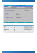
Страница 62: ...COMe cBT6 User Guide 60 System Information...

Страница 63: ...USB Enabled Disabled Enable Disable all BIOS support for USB in order to reduce boot time Note that this will prevent using a USB keyboard in setup or a USB biometric scanner such as a fingerprint rea...

Страница 64: ...d Enable the UEFI boot Legacy Boot Enabled Disabled Enable the Legacy boot Boot in Legacy Video Mode Disabled Enabled Enable to force the display adapter to switch the video mode to Text Mode 3 at the...

Страница 65: ...COMe cBT6 User Guide 63 Platform Information...

Страница 66: ...COMe cBT6 User Guide 64 7 5 2 Advanced Feature Options Description OS Selection Windows Linux Android Select the Operating System family to be booted...

Страница 67: ...Eco mode Reduces supply current in Soft Off S5 to less than 1mA If enabled power button is the only wake up source in S5 See chapter S5 Eco for further details Smart Battery Configuration Disabled Aut...

Страница 68: ...elay Select Action for first Watchdog stage Assert WDT Signal Enabled Disabled Enable Disable assertion of WDT signal to baseboard on stage timeout Stage 1 Timeout 1s 5s 10s 30s 1m 3m 10m 30m Select T...

Страница 69: ...s Range 20 80 C Fan Speed 70 Manual fan speed in Minimum value is 30 in Manual mode only Trip Point Speed 50 Fan speed at trip point in Minimum value is 30 Fan always runs at 100 at Tjmax 10 C Referen...

Страница 70: ...og Module Temperature Determines the temperature source which is used for automatic fan control Widerange Vcc x xx V Shows the Module Main Input Voltage 5 0V Standby x xx V Shows the 5V Standby Voltag...

Страница 71: ...nable Disable Disabled for Windows XP Bi directional PROCHOT Enable Disable When a processor thermal sensor trips either core the PROCHOT will be driven If bi direction is enabled external agents can...

Страница 72: ...able to automatically allow processor cores to run faster then the base operating frequency if it s operating below power current and temperature specification limits This option is only valid for CPU...

Страница 73: ...tchable Hybrid Graphics RC6 Render Standby Disable Enable Enable or Disable Render Standby support GTT Size 1MB 2MB Select the GTT Memory Size of IGD Aperture Size 128MB 256MB 512MB Select the Graphic...

Страница 74: ...024 600 1 18 WSVGA 1024 600 1 24 Custom PAID Select LFP used by Internal Graphics Device by selecting the appropriate panel setup item Backlight Control None External PWM PWM Inverted I2C I2C Inverted...

Страница 75: ...COMe cBT6 User Guide 73 Mode Persistence Disabled Enabled Enables Disables Mode Persistence Center Mode Disabled EFP Select the Display Device that should be centered...

Страница 76: ...e cBT6 User Guide 74 System Component Feature Options Description PNP Setting Disable Power Performance Ax Stepping Bx Stepping Select PNP setting mode Disable Performance Power or Power Performance m...

Страница 77: ...COMe cBT6 User Guide 75 LAN Configuration Feature Options Description PXE ROM Disabled Onboard only Addon only Both Enable Disable PXE Option ROM execution for onboard LAN...

Страница 78: ...COMe cBT6 User Guide 76 South Cluster Configuration...

Страница 79: ...cBT6 User Guide 77 PCI Express Configuration Feature Options Description PCIe Speed Auto Gen1 Gen2 Select PCIe Speed to Gen1 or Gen2 PCI Express Root Port Disable Enable Control the PCI Express Root...

Страница 80: ...ed for OS with external Driver e g Windows 7 Enabled is recommended for OS with integrated USB 3 0 Support e g Windows 8 Please note the USB HSIC Hub for COMe USB Ports 4 7 is linked to xHCI controlle...

Страница 81: ...troller HDAudio Docking Support Enable Enable Disable Enable Disable HDAudio Docking Support of Audio Controller HDAudio PMCE Enable Enable Disable Enable Disable Power Management capability of Audio...

Страница 82: ...rt SATA Test Mode Disable Enable Enables or Disables the SATA Test Mode Chipset SATA Mode IDE AHCI IDE compatibility mode disables AHCI AHCI supports advanced SATA features such as NCQ Warning do not...

Страница 83: ...R50 Support Disable Enable Enable Disable DDR50 speed mode for eMMC eMMC HS200 Support Disable Enable Enable Disable HS200 speed mode for eMMC For eMMC full speed operation the HS200 mode should be en...

Страница 84: ...sable Enable Boot time calculation with High Precision Event Timer enabled State After G3 S0 State S5 State Specify what state to go to when power is re applied after a power failure G3 state S0 Power...

Страница 85: ...Feature Options Description Event Log Disable Enable Enables or Disables the SMBIOS Event Log Mark SMBIOS events as read Enter Mark SMBIOS events as read Marked SMBIOS events won t be displayed Clears...

Страница 86: ...COMe cBT6 User Guide 84 View SMBIOS event log...

Страница 87: ...0 Disabled Enabled Enable or Disable SIO Serial Port Base Address 3F8 2F8 3E8 2E8 Configure Serial Port Base Address IRQ 3 4 5 6 7 12 Configure Serial Port IRQ SIO Serial Port 1 Disabled Enabled Enab...

Страница 88: ...ble or Disable Serial Port COM 0 Base Address 3F8 2F8 3E8 2E8 Configure Serial Port Base Address IRQ 3 4 5 6 7 12 Configure Serial Port IRQ Serial Port 1 Disabled Enabled Enable or Disable Serial Port...

Страница 89: ...Action No Change Enable Disable Activate Deactivate Clear Enable and Activate Disable and Deactivate Set Owner Install with state True Set Owner Install with state False Enable Activate and Set Owner...

Страница 90: ...COMe cBT6 User Guide 88 7 5 4 Boot...

Страница 91: ...COMe cBT6 User Guide 89 7 5 5 Exit...

Страница 92: ...r made solutions based on highly reliable state of the art embedded technologies Kontron provides secure and innovative applications for a variety of industries As a result customers benefit from acce...

Отзывы: