background image

E-3

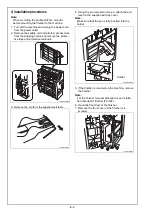
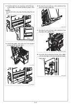
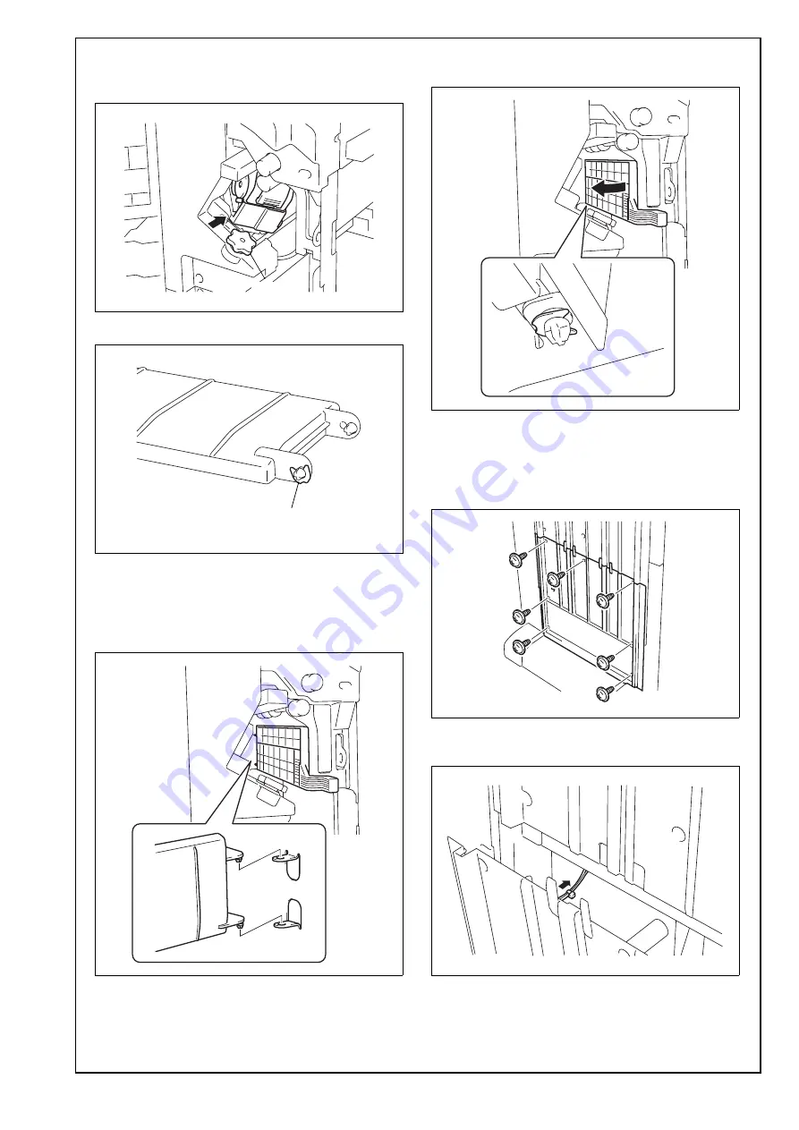
8. If the stapler unit is positioned toward the front of 

the finisher, move it to the rear turning the dial 
shown in the illustration.

9. Remove the C-clip from the supplied guide plate.

10. Attach the guide plate to the finisher.

Note:

Insert the two projections located at the end of the 
guide plate into the holes on the plate inside the 
finisher.

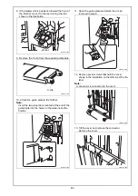
11. Open the guide plate and attach the C-clip 

removed in step 9.

12. Remove seven screws that hold the cover 

shown in the illustration on the left side of the fin-
isher. 

Note:

A connector is connected to the cover.

13. Tilt the cover and remove the connector. 

Remove the cover.

A3ERIXC010DA

Dial

A3ERIXC011DA

C-clip

A3ERIXC012DA

A3ERIXC013DA

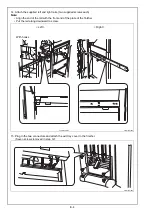
A3ERIXC014DA

A3ERIXC015DA

Содержание SD-511

Страница 1: ...different in shape from yours In that case instead of the illustrations use the appearance of your machine to follow the installation procedure This does not cause any significant change or problem wi...

Страница 2: ...ective materials 3 Remove the pin from the supplied exit lever 4 Using the pin removed in step 3 attach the exit lever to the supplied exit tray cover Note Make sure that the pin is fully inserted int...

Страница 3: ...ctions located at the end of the guide plate into the holes on the plate inside the finisher 11 Open the guide plate and attach the C clip removed in step 9 12 Remove seven screws that hold the cover...

Страница 4: ...lign the end of the rail with the front end of the plate of the finisher Put the rail along downward to screw 15 Plug in the two connectors and attach the exit tray cover to the finisher Seven screws...

Страница 5: ...slightly bending the front side of the rail Note Make sure that the guide plate described in step 11 is opened Put the saddle unit close to the rail and move the saddle unit parallel to the rail Be c...

Страница 6: ...he rails one supplied screw each for left and right 20 Remove the screw shown in the illustration from the front of the saddle unit 21 Remove the screw shown in the illustration from the back of the s...

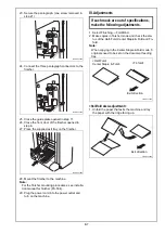
Страница 7: ...into the power outlet and turn on the machine III Adjustments 1 Select Finishing Fold Bind 2 Make copies in finisher mode and check the sta tus of the Half Fold Center Staple Fold and Tri fold Note Wh...

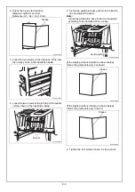
Страница 8: ...late assy shown in the illustra tion and adjust the skew Note Incline the guide plate assy forward or backward according to the deviation of the crease If the staple positions deviate as shown below I...

Страница 9: ...e the Service Manual 5 Touch Finisher 6 Touch FS FN adjustment 7 Touch Half Fold Position 8 Check that ALL is displayed in reversed If the crease deviates as shown below Using the key set the numeric...

Страница 10: ...ce Manual 4 Touch Finisher 5 Touch FS FN adjustment 6 Touch Center Staple Position 7 Check that ALL is displayed in reversed If the Staple positions deviate as shown below Using the key set the numeri...

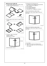
Страница 11: ...screen 10 Make copies again and check the first fold posi tions deviate Second fold position adjustment 1 Display the Service Mode screen For details of how to display the Service Mode screen see the...

Отзывы:

Похожие инструкции для SD-511