E-8
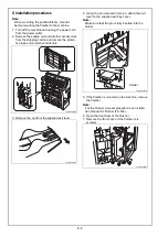
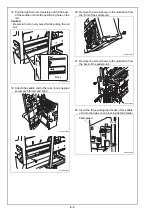
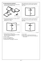
2. Check the crease for deviation
(Measure width A1 and A2).
Reference: A1 - A2 = 0 ± 1.0 mm
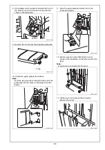
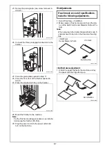
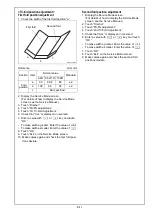
3. Loose the two screws at the right side of the sad-
dle unit as shown in the illustration below.
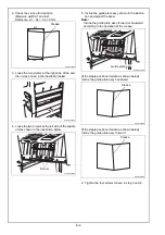
4. Loose the two screws at the left side of the saddle
unit as shown in the illustration below.
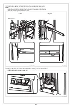
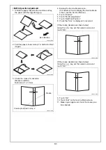
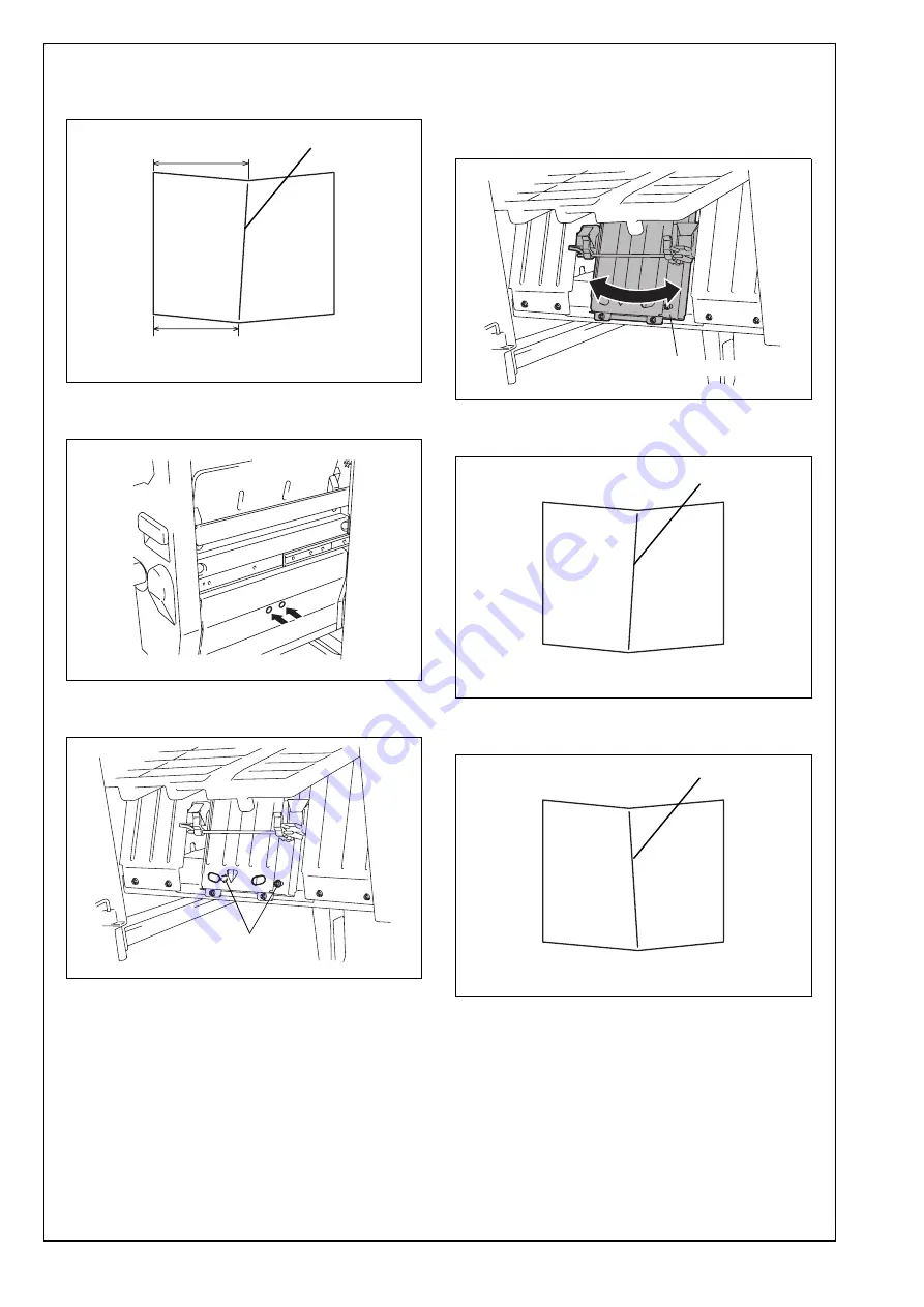
5. Incline the guide plate assy shown in the illustra-
tion and adjust the skew.
Note:
Incline the guide plate assy forward or backward
according to the deviation of the crease.
[If the staple positions deviate as shown below]
Incline the guide plate assy backward.
[If the staple positions deviate as shown below]
Incline the guide plate assy forward.
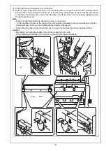
6. Tighten the four screws loosen in step 3 and 4.
A10DIXC034DB
A1
A2
Crease
A3ERIXC029DA
A3ERIXC030DA
Screw
A3ERIXC031DB
Guide plate assy
Crease
A10DIXC039DB
A10DIXC040DB
Crease


