background image

Operation

Context

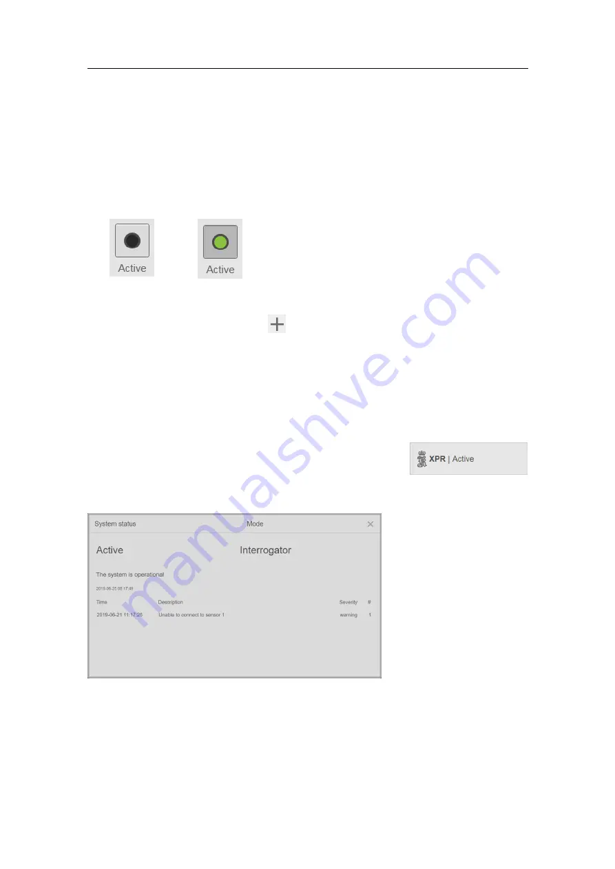
You activate the Sensor Unit by enabling or disabling the

Active

button. A green circle in

the

Active

button indicates that the system is active. After some time without receiving

any data, the XPR system will automatically return to

Standby

mode.

Standby mode

Active mode

Procedure

1

Select the

System menu

button,

, to open the

System

menu.

2

Select the

Active

button.

Related topics

Active

on page 22

Checking the system status

The

System status

box, located at the top left of the

Main

view, shows the overall XPR system status. Here you can
observe if the system is operating as intended.

Context

Status text colour

The colour of the text in the

System status

box indicates how the system is operating.

Red

: the system is not operating as intended.

Yellow

: the system has detected warnings or reduced operability.

Grey:

Info message or inactive Warning/Alarm.

XPR-D-User/1.0

15

Содержание XPR 100

Страница 1: ...Operator Manual XPR 100 Long Range Relative Positioning System...

Страница 2: ......

Страница 3: ...XPR 100 Long Range Relative Positioning System Operator Manual XPR D User 1 0 July 2019 Kongsberg Seatex AS...

Страница 4: ...ex AS endeavours to ensure that all information in this document is correct and fairly stated but does not accept liability for any errors or omissions Warning The equipment to which this manual appli...

Страница 5: ...m 11 Operating procedures 12 Confirming that the system is active 12 Selecting a target 12 Adding a new target 13 Editing a target 14 Setting the system to Active or Standby mode manually 14 Checking...

Страница 6: ...ting the system software 39 Checking the product version 40 Periodic maintenance 40 Cleaning of Processing Unit air inlet 40 Cleaning of Sensor Unit cover 41 Inspecting the Remote interface cabinet 41...

Страница 7: ...rget audience This manual is intended for personnel operating the XPR system License information The XPR is not a licensed product but a national license for the use of radio frequencies is required f...

Страница 8: ...ystem an extended operational area of up to 360 and avoid blind angles The system can be interfaced to remote systems such as Dynamic Positioning Either through Ethernet or serial lines Configuration...

Страница 9: ...r and data cable Pigtail fixed to Sensor Unit B Power cable Junction box to Remote interface cabinet C Ethernet cable Junction box to Remote interface cabinet D Power cable to Remote interface cabinet...

Страница 10: ...Unit or the Sensor Unit housing has been opened by the customer Incorrect power connection Restrictions in use The operation sector for a single Sensor Unit is 100 degrees If the vessel exceeds the o...

Страница 11: ...ich the receiver is connected Consult the manufacturer or dealer for help Network security Equipment manufactured by Kongsberg Seatex AS is frequently connected to local area networks LAN Connecting a...

Страница 12: ...The customer end user of the system will always be in charge of defining and implementing a security policy and providing the relevant network security applications Note Kongsberg Seatex AS will not a...

Страница 13: ...r source Procedure 1 Check that the S1 switch on the Local interface rail is ON 2 Verify that Q1 is switched ON if Q1 is used to power the system monitor 3 Turn on the Processing Unit by pressing the...

Страница 14: ...operation Related topics Active on page 22 Selecting a target By selecting a target you specify the frequency pair and address code you want to use If you want to use a specific pair and address code...

Страница 15: ...add a new target Context Procedure 1 Select the System menu button to open the System menu 2 Select Tools Target Editor 3 Select New 4 Enter values in each box Important The Id must be unique Frequen...

Страница 16: ...lues you want to change Important The Id cannot be changed Create a new target if you want to use a different Id Frequency pair and Address code must be correct for the system to function properly 6 S...

Страница 17: ...System menu 2 Select the Active button Related topics Active on page 22 Checking the system status The System status box located at the top left of the Main view shows the overall XPR system status H...

Страница 18: ...h for transponders within range If a transponder is within range the system will display data The system is in standby and operational No tracking of transponders takes place and no data is displayed...

Страница 19: ...llustrated Day white Day black Night Related topics Palette on page 24 Scaling the Radar view The Radar view supports scaling Press the key or key to zoom the Radar view one step in or out respectivel...

Страница 20: ...nit Related topics Activating the configuration parameters on page 19 Display on page 24 Enabling remotely controlled palette You can manually select any colour palette directly on the XPR system but...

Страница 21: ...cursor will disappear after some time of mouse inactivity Simply move the mouse to make the cursor reappear The XPR is operated and set up from the System menu Activating the configuration parameters...

Страница 22: ...on of the various functions The active button is indicated with a dashed line Press the Tab key to change the active buttons Press Enter to open the function linked to the various buttons Press the Sp...

Страница 23: ...dar view D System menu button Provides various system settings and operational functions E Main view The Main view shows the Radar view in this illustration You can toggle the Radar view and the Range...

Страница 24: ...rack it Target Target allows you to select which target you want to search for and track Target selection Target selection allows you to select between Automatic or Manual mode When you are in Manual...

Страница 25: ...hich target you want to search for and track from a list of targets How to open Select the Target button on the System menu to open the Select target dialog box Details Name The name of the target Id...

Страница 26: ...s deselected in the DP system or DARPS system the XPR system will automatically enter Standby mode Manual Select Manual mode to manually select a target and manually set the system in Standby or Activ...

Страница 27: ...d Remotely controlled palette When this option is turned on the XPR system will automatically change palette when the palette is changed on the external system which transmits the palette information...

Страница 28: ...mmunication type Select between Serial or UDP IP Serial Port or UDP Port Select which port you want to use from the list Cable ID You can give the cable a name for identification purposes This is opti...

Страница 29: ...t Cable ID You can give the cable a name for identification purposes This is optional Add Output Select Add Output to add more output ports You can add two output ports Delete Output Select Delete Out...

Страница 30: ...or your vessel Length Type the length of your vessel in metres Width Type the width of you vessel in metres About About holds the XPR system software version How to open To open the About page select...

Страница 31: ...they are not described in this document Caution This is an expert feature and should be used with extreme care Do not alter or delete information without consulting with Kongsberg Seatex AS customer s...

Страница 32: ...rget to the Target list and to edit a target How to open To open the Target Editor select the System menu Tools Target Editor Details Name The name of the target Id There is a unique id of each target...

Страница 33: ...ch is not in the Target list you can add a new target How to open To open New Target select the System menu Tools Target Editor Select New Details Id There is a unique id of each target This id is the...

Страница 34: ...idth of the target in metres Dist from stern center keel This is the location of the Sensor Unit of the remote vessel relative to stern centre line and keel Related topics Target Editor on page 30 Add...

Страница 35: ...dentifies the transmit and receive frequencies of the XPR system Address code This is a number which is used to separate systems which use the same frequencies Length Width This is the length and widt...

Страница 36: ...cated to the left in the Main view Select System status to open the System status view Details Select the System status button to show additional operational information If there are any events they w...

Страница 37: ...or Info It indicates the number of times this event has occurred Related topics Checking the system status on page 15 Target information and target history Target information holds the name of the sel...

Страница 38: ...ich is used to separate systems which use the same frequencies Signal It indicates the signal strength RNG It shows the distance to target for the last 30 minutes BNG It shows the bearing to target fo...

Страница 39: ...the Sensor Unit on the other vessel AZM AZM is the Azimuth which is the relative bearing from the Sensor Unit on the other vessel to the Sensor Unit on own vessel Related topics Radar view on page 37...

Страница 40: ...operating angle the XPR system will not be able to indicate range or bearing and the remote vessel will disappear from the Radar view If the remote vessel moves inside the operating angle again it wil...

Страница 41: ...mage or degradation of the units and void the warranty Damaged units have to be shipped back to Kongsberg Seatex AS for repair Note Preferably equipment should be returned in its original package Unit...

Страница 42: ...em software version and the software version 3 Select Details to show detailed information about the system Such as serial numbers Sensor Unit software version etc 4 Close the page to return to the Ma...

Страница 43: ...ar intervals depending on use and ambient conditions At least once a year Procedure 1 Check the door hinges for ease of movement Spray with a suitable water free lubricant 2 Check the door lock for ea...

Страница 44: ...e Procedure 1 If possible backup the recent configuration on your Processing Unit to a USB flash drive Follow the procedures in the XPR Installation Manual System backup and restore 2 Disconnect the P...

Страница 45: ...e XPR Installation Manual to configure the replacement unit If the IP address of the replacement Sensor Unit conflicts with an existing Sensor Unit s IP address you must change IP address of the repla...

Страница 46: ...connector and turn the power switch on WARNING If the fuse has blown the cause for the fuse failure must be investigated Troubleshooting Checking the signal history If you are experiencing an unstabl...

Страница 47: ...elect the Target information box 2 Observe the graphs for information on signal range and bearing 3 Close the Target history view when finished Related topics Target information and target history on...

Страница 48: ...2019 Kongsberg Seatex...

Отзывы: