38
413764/B
A
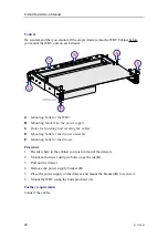
Earth strap
B
Bolt this shock absorber to the bulkhead.
C
Secure the shock absorber assembly to the top of the cabinet using these two bolts.
All cables will enter through the bottom and/or the top of the cabinet.
Procedure
1
Prepare the installation of the cabinet.
a
Observe the outline dimensions drawing.
The drawing is located in the
Drawing file
chapter in this manual.
Note
The outline dimensions drawing shows the initial size of an empty cabinet.
When the cabinet is completed for normal operation, the weight will compress
the bottom shock absorbers slightly. You must take this into consideration
when you plan the mounting.
b
Determine the location of the unit.
c
Verify that the location meets the sonar room requirements
d
Verify that the location meets the environmental requirements defined for
the EA640.
e
Verify that the location is within range of the transducer cables.
f
Verify that the location offers ample space around the cabinet to allow for
cables, maintenance and parts replacement.
g
Determine the installation method.
h
Make all necessary installation drawings.
i
If relevant, design and manufacture bulkhead support bracket(s) and/or "U"
shaped steel profiles.
EA640 Installation Manual
Содержание EA640
Страница 62: ...62 413764 B 388697 WBT outline dimensions EA640 Installation Manual ...
Страница 63: ...413764 B 63 Drawing file ...
Страница 64: ...64 413764 B 400930 WBT Cabinet outline dimensions EA640 Installation Manual ...
Страница 65: ...413764 B 65 Drawing file ...
Страница 66: ...66 413764 B EA640 Installation Manual ...
Страница 67: ...413764 B 67 Drawing file ...
Страница 93: ......
Страница 94: ... 2018 Kongsberg Maritime ...

