background image

47

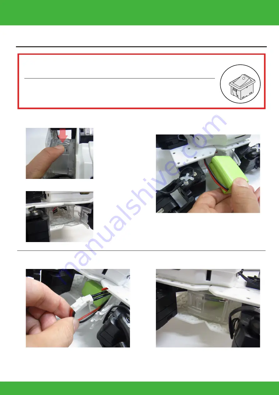
Battery Mounting

Mount the battery.

※Reference photo: KXR-L4

Before installation, check to be sure the power switch is OFF.
Do not turn the power switch ON until connecting to the PC. 

OFF

Always read through the battery and charger manuals before use. Also, if using an LiFe 
battery, to prevent damage from over discharge, be sure to read about  Motion when voltage 
reduced (voltage check function on HTH4)  after the instructions for running motions. 

①-1.Push down lightly on the hatch clasp and slide it.

②Put in the battery in the direction of the 

  photo so the connector goes in first.

③Connect the connector.

④Close both sides of the hatch to complete 

 the process.

①-2.Once unlocked, the hatch opens on both sides.

*Do not force the battery in. Check to see if it s 

  catching on a cable.

*Be sure the polarity is correct. Connect cables of the 

 same color so that the clasps join.

Содержание KXR-L4R

Страница 1: ...Turtle Rover Type KXR L4T R L4T L4R Assembly Manual Service Dept KONDO KAGAKU Co Ltd support kondo robot com Support Information www kondo robot com Ver 2 0 2017 Kondo Kagaku Co Ltd...

Страница 2: ...pe 16 Robot Assembly 17 Full Robot Assembly Procedures 17 Servo ID Setting 18 Body Assembly 21 Leg Assembly Turtle Type 30 Attaching All Parts Turtle Type 33 Wheel Assembly Rover Type 38 Attaching All...

Страница 3: ...lt our service section Do not disassemble or modify the servo or board of the finished product Disassembly and repair other than those stated in this Instruction is prohibited Incorrect disassembly or...

Страница 4: ...this product as an assembly kit the motion of the assembled product cannot be guaranteed Further due to the fact that the movements of the assembled product depend in large part on the method by whic...

Страница 5: ...No 02303 x4 x1 x2 x2 x2 x1 x1 x1 A C B Body Panel Lock Ring Cap Lock Ring BT Box Plate BT Side Plate BT Hatch Back Pack Cover Back Pack Base No 02313 No 02313 No 02312 No 02312 No 02313 No 02311 No 0...

Страница 6: ...Kit Guidance Length 100mm Length 1 5m Length 160mm x1 Board Battery Charger Accessories M2 4 M2 6 M2 8 Low Head Screw No 02327 M2 12 M2 6 10 2 6 4 M3 6 M3 8 0 x28 x14 x8 x1 x4 x31 x16 x8 1 Bind Head Z...

Страница 7: ...BT Hatch Back Pack Cover Back Pack Base No 02313 No 02313 No 02312 No 02312 No 02313 No 02311 No 02313 No 02311 x1 x1 D Dummy Servo Upper Dummy Servo Bottom No 02309 No 02309 x4 x4 E Upper Arm 3300 2...

Страница 8: ...Kit Guidance Length 100mm Length 1 5m Length 160mm x1 Board Battery Charger Accessories M2 4 M2 6 M2 8 Low Head Screw No 02327 M2 12 M2 6 10 2 6 4 M3 6 M3 8 0 x12 x10 x4 x5 x4 x63 x32 x8 1 Bind Head Z...

Страница 9: ...IO serial ports for each of two systems of ICS3 0 3 5 3 6 compliant devices and can connect up to 36 ICS3 0 3 5 3 6 devices There are also five AD analog ports so gyro acceleration and other analog se...

Страница 10: ...it cannot be damaged by impact due to falling etc before turning the switch on If the battery appears damaged due to impact or if it appears unusual in any way do not use or recharge it Repeated use...

Страница 11: ...3304 ICS Blue This kit uses M2 screws Serration Middle Case Bottom Case ZH connector Whichever it is connected to there is no impact on operations Part Name of Servo Motor KRS 3300 Series Origin M3 S...

Страница 12: ...t an angle Right Right Tighten while applying pressure If you strip the screw head remove the screw without applying too much force and then use a new screw Do not use damaged screws If the screw beco...

Страница 13: ...e M2 end Joint nut screw hole How to set Joint Nuts Double Joint Base When installing joint bases Make sure the installation direction is correct Front Side Horn Side Back Side Nuts Side Joint Base Jo...

Страница 14: ...nstallation bearings and the length of the arms are correct Arm 20 Caution Cross upper arm 28 is exclusively with the cross upper frame 20mm Set Back 26mm 38mm Serration Free Free There are no screw h...

Страница 15: ...on properly Servo ID stickers are classi ed with the symbols and Always connect ID 0 to the SIO5 7 system The explanations in this manual use the following wiring layout Putting on Connection Cable De...

Страница 16: ...CB 4mini using ZH ZH connection cable RCB 4mini s SIO ports servo connectors are divided into two systems SIO1 3 and SIO5 7 Within the same system changing the port does not impact operations but be a...

Страница 17: ...T R Multiuse parts 1 Neck 2 BT Battery Box 3 Joining 1 Leg assembly T 1 Change servo mode 2 Wheel assembly R 1 Legs T 2 Electronic compnents Reference diagram 1 Wheels R 2 Electronic compnents Procedu...

Страница 18: ...ion Dual USB Adapter HS Serial Extension Cable Servo ZH Conversion Cable Be aware that the cable used for connection di ers from the software manual Connect the servos to the Dual USB Adaptor HS and s...

Страница 19: ...M Con rmation In the image COM 1 is selected but the COM number di ers depending on the computer you use so always select the con rmed number 4 Set the speed for servo communica tions If you select Au...

Страница 20: ...he Dual USB Adaptor HS from the PC after closing the software This process is only for changing settings so communications use the PC s bus power but when con rming operations connect the battery Refe...

Страница 21: ...nut screw holes cut use two to attach the backpack cover The others can also be used as nuts so store them Gather and assemble the parts for T Turtle R Rover Unused parts can also be used later when...

Страница 22: ...ID 0 x1 Bottom spacer x1 Assembled Arm supporter 3300B x1 Supporter B spacer 2 x1 Joint base x1 Joint Nut x1 Horn B x1 M2 4 x4 M2 8 x4 M3 8 x1 Bottom spacer Case screw x4 M2 8 x4 Supporter B spacer 2...

Страница 23: ...Upper Shaft A When the origin deviates with the diagram position lightly insert the arm and rotate to adjust the position Attach it straight toward the A line Use M3 8 Make sure the screw length is co...

Страница 24: ...der the hook 2 Pull the cable to the length indicated below Wire four ZH connection cables of 160 mm to the BT box plate BT Box plate x2 BT Side plate x2 BT Hatch x2 M2 6 x2 ZH connection cable 160mm...

Страница 25: ...it is easy to view Attach the plate on the opposite side so that it sandwiches the two BT hatch plates BT Hatch x2 If installation proves di cult try temporarily securing the BT box plate and insertin...

Страница 26: ...servo unit x1 Assembled M2 8 x4 M2 12 x4 M2 6 x6 M2 8 x12 M2 12 x8 M2 6 10 x4 ZH Connection cable 120mm x1 Attach the part with the cut M2 so that it comes to the outer side of the panel Assembled on...

Страница 27: ...iring through the BT Leg pate Leg plate Lock ring Back pack BT Box side Body part top side Lock Align the notch and protrusion and attach Rotate until it clicks into place About the lock portion for t...

Страница 28: ...t frame 3300B b Origin 1 2 1 1 2 In side connecter Attach four cables In to the Backpack Apply the decal to the cable 120mm M2 6 10 x2 Dammy servo Upper shaft M2 6 x4 Be careful of the protruding dire...

Страница 29: ...29 Body Assembly 3 Joining KXR L4T R Rotate until it clicks into place Attach case screws Body Body panel Lock ring cap Lock ring Case screw x8 Case screw x8 Detach case screws...

Страница 30: ...ly is completed proceed from Battery Mounting on p 47 to Connection with PC Rover To p 38 Change to Rotation mode wheel servo When main unit assembly is completed proceed from Battery Mounting on p 47...

Страница 31: ...6 x4 Bottom arm 3300 20 x4 Joint frame 3300A x8 Joint base A x4 Assembled Joint base C x4 Assembled M2 6 x4 M2 6 10 x20 M3 6 x4 2 6 4 x4 Assenble the four sets Joint base A Joint base C Joint frame 33...

Страница 32: ...32 Leg Assembly 2 M2 6 x2 Side with no connectors Detach case screws Bottom Arm 3300 20 Leg Assemble four sets Joint frame 3300A M2 6 10 Case screw x2 M2 6 10 KXR L4T...

Страница 33: ...Attach the Turtle legs Cable guide X For the cable whichever connector is used it has no e ect on operations but make sure the cable does not overlap 120mm Attach the four legs to the body Right Legs...

Страница 34: ...moving the robot ZH type 3PIN ZH type 3PIN x12 VH type 2PIN To RCB 4mini VH type 2PIN VH type 2PIN To power switch To Battery The white circle side is power ON The power is normally OFF unless the ro...

Страница 35: ...ure the direction is correct To Battery box To RCB 4mini To COM port at RCB 4mini Attach so that the white wire comes up 1 Attach RCB 4mini Attach the electronic components 2 Attach ZH Conversion cabl...

Страница 36: ...te SIO port Green AD port VH type 2PIN ZH type 3PIN ZH Conversion cable Be careful of the protruding direction and do not force it in Be sure to con rm the lock guide direction and that it is not conn...

Страница 37: ...37 Complete Assembly completed Proceed from Battery Mounting on p 45 to Connection with PC KXR L4T...

Страница 38: ...ected but the COM number differs depending on the computer you use so always select the confirmed number 2 Set the speed for servo communica tions If you select Auto it will auto matically connect in...

Страница 39: ...of the window 5 Press the Write button When the Write Suc cessful dialog box is displayed the process is complete Close the dialog box by pressing the OK button The above is the method for changing Ro...

Страница 40: ...60 x4 Bottom spacer x4 Assembled Joint base C x4 Assembled Horn B x4 M2 6 x40 M2 8 x16 M2 6 10 x4 M3 8 x4 Assemble the wheel and tire Assenble 4 sets Tire 60 Wheel 60 x2 Make sure positions Detach ca...

Страница 41: ...ll rotation mode so it doesn t matter if the origin position is out of alignment Bottom arm 3300 26 Joint base C M2 8 x4 Wheel Assemble 4 sets M2 6 10 M2 6 x4 M3 8 Attach M3 8 after tightening M2 4 Wh...

Страница 42: ...h to Bottom side Attach the four wheels to the body Right Wheel Left Wheel Attach the upper arm to the body servo Attach the four wheels to the body Attach four cables 2 6 4 M2 6 10 120mm Assemble par...

Страница 43: ...e PC and moving the robot ZH type 3PIN ZH type 3PIN x12 VH type 2PIN To RCB 4mini VH type 2PIN VH type 2PIN To power switch To Battery The white circle side is power ON The power is normally OFF unles...

Страница 44: ...r make sure the direction is correct To Battery box To RCB 4mini To COM port at RCB 4mini Attach so that the white wire comes up 1 Attach RCB 4mini Attach the electronic components 2 Attach ZH Convers...

Страница 45: ...e PC White SIO port Green AD port VH type 2PIN ZH type 3PIN ZH Conversion cable Be careful of the protruding direction and do not force it in Be sure to con rm the lock guide direction and that it is...

Страница 46: ...46 Complete KXR L4R Assembly completed Proceed from Battery Mounting on p 45 to Connection with PC...

Страница 47: ...o read about Motion when voltage reduced voltage check function on HTH4 after the instructions for running motions 1 Push down lightly on the hatch clasp and slide it Put in the battery in the directi...

Страница 48: ...vos and robot to communicate with the PC via a USB connection In the following adjustments are made to the robot using a computer When all the processes are completed the robot will begin to walk Cond...

Страница 49: ...art4 Software To install the software double click the setup exe in the HeartToHeart4 folder in the KXR folder to automatically run the setup program Continue the installation process as instructed by...

Страница 50: ...oject example 4 Copy Sample Data Turn the KXR power switch ON 5 Activate KXR IMPORTANT Check the RCB 4 wiring and each servo motor once again be foreturning the power ON Turning the power ON with conn...

Страница 51: ...ilateral symmetry If you run a motion with the trim out of alignment the robot will not function properly or topple over easily so make sure to perform the process carefully Trim Adjustment Types of P...

Страница 52: ...New Project window be comes the same as the name of the folder that was imported If no change is made press OK 5 Assign the Communication Port COM number to be used This will typically be the COM numb...

Страница 53: ...ication rate and ICS communication rate to 115200 Read the cautions on the next page before pressing the RAM button 6 Press the Project Setting Window but ton The Project Setting window opens when sel...

Страница 54: ...ine and correct the part that is off track Proceeding to set the Home Position without confirming this posture can cause damage to the servo motors Make sure that the robot assumes this posture before...

Страница 55: ...10 Press the Sync button in the toolbar of the Main Window If the color of the button changes after pressing it is turned ON In the Sync state the corresponding servo motor operates on a real time ba...

Страница 56: ...e side completely and then use that as the standard when adjust ing the opposite side KXR L4T KXR L4R Align the leg servos so that when looked at from the side their output shafts are lined up in a st...

Страница 57: ...ed a confir mation dialog asking Do you want to restart your computer to reflect the changes made will appear press OK PC HTH4 will not restart When restarting all of the robot servos will relax To pr...

Страница 58: ...Play button is pressed so please be careful 4 Save Project before quitting the soft ware Press the Save Project button in the toolbar of the Main Window To play other motions repeat steps 2 to 3 If y...

Страница 59: ...otion assigned to the button data is sent to the robot by pressing the button shown in the window For detailed instruc tions please refer to HeartToHeart4 User s Manual For usage details refer to the...

Страница 60: ...he KRC Command er window The KRC Commander screen opens Motions can be assigned to each button and operated Refer to the sample motion assignment list at the end of this section 2 Click the Send ON OF...

Страница 61: ...ormed by con tinuing to click the button 4 Click LockKey when executing a combination of buttons With LockKey clicked when you press a button it will stay down When you press it again it will release...

Страница 62: ...2306 2114 16 0 0 S2 S4 S1 S1 S1 S1 S3 S3 S3 S3 0 0 0 0 1 2 8 4 1024 4096 513 514 64 256 16 0 0 S2 S4 S1 S1 Walking Moving RC Walking RC Moving Shake Head Flapping Move Motion Move Motion Basic Motion...

Страница 63: ...n to expand a project Reading Project This completes the instructions for assembly and running motions For software operation instructions refer to the HeartToHeart4 User s Manual Always check the Red...

Страница 64: ...e this setting before use 1 Set the project and open the project window The voltage per cell cannot drop below 3 0V so 3 0V x 2 cells is 6 0V Set the motion to run when power voltage drops below the v...

Страница 65: ...ree angle Dummy servo for servo replacement Sole grips sold separately can be attached to the underside Set of panels for securing servos and making the body Backpack for installing electronic compone...

Страница 66: ...r KRS 3301 3302 For KRS 3301 3302 Upgrade servo Same size as 3301 For KRS 3304 For KRS 3304 For KRS 3300 series Standard control board for KXR Connect to Robot from PC Connect to RCB 4mini from Dual U...

Страница 67: ...le motion uses the port in the diagram If a servo is connected remove it and connect it to the KRR 5FH port It does not matter which of KRR 5FH s SIO ports is used it has no impact on operations Also...

Страница 68: ...sor 2 USRX 1 Sensor base Bottom arm Can use 20 26 or 38 The joint base can be attached to the necessary area whether body or neck etc Can also use M2 6 10 M2 Nut x2 Can also be attached by reversing t...

Страница 69: ......

Отзывы: