


8
TT-1303
7/02
4.3
Flush-mount
remote
annunciator
initial
installation.
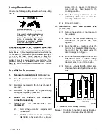
4.3.1
Prepare the mounting site by creating an
opening in the wall for flush mounting the
remote annunciator.
Note:
Mount
the
remote
annunciator
inside a standard 30 x 20 x 10 cm
(12 x 8 x 4 in.) pull box installed in the
wall.
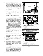
4.3.2
Disassemble the remote annunciator box.
Remove six drill screws to disassemble
the side panels and separate the front and
back remote annunciator panels. Retain
the drill screws (X-794-2) for reassembly.
Discard the side panels.
4.3.3
Proceed to step 5, Wire the remote
annunciator.
5.
Wire the remote annunciator.
5.1
The installer must supply all leads between the
14-relay dry contact assembly (A-293983) and the
remote annunciator (A-258782). Isolate the leads
from all other voltages. Observe the following
guidelines during installation:
D
Use
separate
conduit
for
the
remote
annunciator leads.
D
Use grounded metallic conduit for leads or use
shielded cable in nonmetallic conduit.
D
Use the 14-relay dry contact kit located at the
generator set for all signal leads and a separate
power source for the remote annunciator.
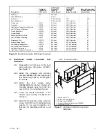
To determine the voltage supply wire gauge for
leads N and 42B, measure the cable distance
between the 14-relay dry contact box and the
remote annunciator. For example, if the cable
distance between the remote annunciator and the
14-relay dry-contact box is 122 m (400 ft), then the
total wire length for each conductor is 122 m
(400 ft). According to the chart in Figure 9, this
example requires 14-gauge wire for leads N and
42B only.
Use stranded or solid 18- or 20-gauge wire for
signal leads (39, 12, 36, etc.) at lengths up to 305 m
(1000 ft.). Never mount the remote annunciator
more than 305 m (1000 ft.) from the 14-relay dry
contact box.
5.2
Attach wiring of the correct length and gauge to
the 14-relay dry contact box. See Figure 9.
5.3
Route the wiring from the 14-relay dry contact box
through the opening in the annunciator back
panel.
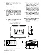
5.4
Attach the leads to the terminal strip. Be sure to
connect the 14-relay dry contact box leads to the
corresponding
terminals
in
the
remote
annunciator. See Figure 10.
5.5
Connect transfer switch terminals 10, 12, and 13
to the remote annunciator terminals 59, N, and 58,
respectively, if the electrical system has a transfer
switch.
5.6
Replace the 14-relay dry contact box cover and
install the four cover screws (X-6216-1).
Leads
Length, m (ft.)
Wire Gauge
0--21
(0--100)
18--20
N, 42B
31--152
(100--500)
14
,
152--305
(500--1000)
10
39, 12, 36, etc.
0--305
(0--1000)
18--20
Figure 9
Wire Specifications Between Remote
Annunciator and Dry Contact Box
6.
Complete the remote annunciator final
installation.
6.1
Proceed to either 6.2, Surface-Mount Remote
Annunciator Final Installation or 6.3, Flush-Mount
Remote Annunciator Final Installation.
6.2
Surface-mount
remote
annunciator
final
installation.
6.2.1
Reassemble
the
front
panel
to
the
annunciator box back panel with two drill
screws (X-794-2).
6.2.2
Reattach the side panels with four drill
screws (X-794-2).
6.2.3
Proceed to step 7.


