


4
TT-1303
7/02
2.2.6
Place the terminal block bracket (347292)
on the underside of the junction box top
panel with the bracket mounting holes
visible from the junction box rear and
mount it using two screws (X-125-3) and
nuts (X-6210-7). See Figure 3.
2.2.7
Reposition the controller over the junction
box holes and install the four screws
removed in step 2.2.2.
2.2.8
Attach the controller connection assembly
(GM13984) to the terminal block bracket
using
six
screws
(X-51-3),
spacers
(X-712-9), and nuts (X-70-12). Place the
spacers between the controller connection
assembly and the mounting bracket.
2.2.9
Plug
the
wiring
connection
harness
(GM17029) into the controller connection
assembly’s P25 connector.
2.2.10 Proceed to step 2.4.
2.3
GM17070-KP3
and
GM17070-KP3S
kits
(450--2000 kW).
2.3.1
Remove the junction box rear panel and
the hardware.
2.3.2
Remove the inner panel access door
screws and swing open the access door.
2.3.3
Attach the controller connection assembly
(GM13984) to the junction box inner panel
studs using six spacers (X-712-9) and nuts
(X-70-12). Place the spacers between the
controller connection assembly and the
mounting bracket. See Figure 4 for the
mounting location.
2.3.4
Plug
the
wiring
connection
harness
(GM16753) into the controller connection
assembly’s P25 connector.
2.3.5
Proceed to step 2.4.
2.4
Remove the controller cover and hardware.
2.5
Route the other end of the wiring connection
harness (GM17029, GM17033, or GM16753)
through the junction box port to the controller
interconnection circuit board.
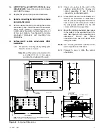
GM17028-A
1. Terminal block bracket screws (X-125-3) and nuts (X-6210-7)
2. Terminal block bracket (347292)
3. Controller connection assembly (GM13984)
4. Detail A, mounting hole dimensions (top view)
4
1
2
3
Figure 3
Terminal Block Bracket and Controller
Connection Assembly Mounting
(350/400 kW)
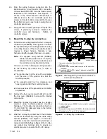
365569A-G/GM16780-A
1. Inner panel access door
2. Inner panel access door screws (6)
3. Controller connection assembly (GM13984)
2
3
1
Figure 4
Terminal Block Bracket Mounting in
Junction Box (450--2000 kW)


