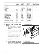
Kohler GM17071-KP1 Скачать руководство пользователя страница 6

6

TT-1303

7/02

3.5

Connect lead P of the wiring harness (256495)
from the 14-relay dry contact box to the battery
positive (

+

) terminal at the starter solenoid.

Lead N of the wiring harness connects to the
battery’s negative (--) terminal at the engine
ground. Cut leads to length, strip ends, and crimp
on ring terminals (X-283-4, 1/4 in. diameter),
(X-283-5, 5/16 in. diameter), or (X-283-32, 1/2 in.
diameter) as required.

Do not use terminals 42A and 2 on the 14-relay dry
contact box terminal strip to supply voltage to the
relay contacts. The user must attach separate
leads directly to the battery for the voltage supply.

If additional load, lights, or alarms are connected
to the 14-relay dry contact box, resize leads P and
N based on the total current requirements.

354246B-

GM13984-

CONTROLLER CONNECTION KIT MOUNTED IN JUNCTION BOX

Figure 7

Remote Annunciator with 14-Relay Dry Contact Kit Connections

Содержание GM17071-KP1

Страница 1: ...stations Read the entire installation procedure and compare the kit parts with the parts list in this publication before beginning installation Perform the steps in the order shown Observe applicable...

Страница 2: ...temperature shuts down the generator set Line Power The lamp illuminates when commercial utility power or other source supplies the power when equipped with an auxiliary contact When the lamp illumina...

Страница 3: ...pped 1 3 Disconnect the generator set engine starting battery ies negative lead first 2 Mount and connect the controller connection assembly 2 1 GM17070 KP1 and GM17070 KP1S kits 20 300 kW 2 1 1 Remov...

Страница 4: ...access door 2 3 3 Attach the controller connection assembly GM13984 to the junction box inner panel studs using six spacers X 712 9 and nuts X 70 12 Place the spacers between the controller connection...

Страница 5: ...location D An area as near to the generator set controller as practical 3 2 Remove the four cover screws X 6216 1 and lift the box cover 256880 to access the internal components 3 3 Mount the 14 relay...

Страница 6: ...5 16 in diameter or X 283 32 1 2 in diameter as required Do not use terminals 42A and 2 on the 14 relay dry contact box terminal strip to supply voltage to the relay contacts The user must attach sep...

Страница 7: ...ctrical box in the wall See Figure 8 for the mounting hole dimensions Protect the remote annunciator from dust and debris when drilling the holes Note Use mounting hardware suitable for the wall compo...

Страница 8: ...total wire length for each conductor is 122 m 400 ft According to the chart in Figure 9 this example requires 14 gauge wire for leads N and 42B only Use stranded or solid 18 or 20 gauge wire for signa...

Страница 9: ...Pressure RDO8 K12 Input K12 NO terminal 63 Low Water Temperature RDO5 K13 Input K13 NO terminal 35 High Engine Temperature Warning RDO6 K14 Input K14 NO terminal 40 Figure 10 Remote Annunciator Kit W...

Страница 10: ...Move the remote annunciator alarm horn switch to SILENCE to stop the alarm horn The respective remote annunciator lamp remains lit 8 3 Disconnect the generator set from the system load with the line c...

Страница 11: ...ing 0 688 x 0 875 in NPT X 634 11 1 Bushing 0 938 x 1 187 in NPT X 634 14 2 Rivet pop 1 8 diameter Al Al X 781 21 4 Screw 10 24 x 0 50 in X 6216 1 1 Fuse 10 amp 223316 1 Box dry contact 226676 1 Holde...

Страница 12: ...1 Bushing 0 688 x 0 875 in NPT X 634 11 1 Bushing 0 938 x 1 187 in NPT X 634 14 2 Rivet pop 1 8 diameter Al Al X 781 21 4 Screw 10 24 x 0 50 in X 6216 1 1 Fuse 10 amp 223316 1 Box dry contact 226676...

Отзывы: