


TP-6196 10/09
83
Section 6 Component Testing and Adjustment
SCR Module Test Procedure
Required equipment:
!
Ohmmeter
!
12-volt test lamp (or voltmeter)
!
12-volt DC power source
!
100--500 ohm resistor
!
Jumper
1. Set the ohmmeter to the R x 1 scale.
2. Connect the ohmmeter from (+) to (--) on the SCR
module. You should read high resistance in one
direction and low resistance in the other (reverse
the leads).
3. Connect the ohmmeter from AC1 to (+) on the SCR
module. You should read high resistance in both
directions.
4. Connect the ohmmeter from AC1 to (--) on the SCR
module. You should read high resistance in one
direction and low resistance in the other.
5. Repeat steps 3 and 4 for AC2.
6. Connect the ohmmeter from G1 to (+) on the SCR
module. You should read low resistance in both
directions.
7. Repeat step 6 for G2.
You should read low
resistance in both directions.
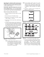
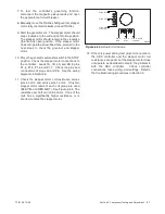
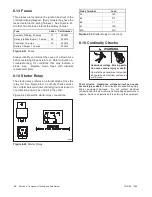
8. See Figure 6-19. Connect the
negative
(--) lead
from the DC power source to the
positive
(+)
terminal on the SCR module.
Note:
The SCR module may be damaged if the
power supply is connected incorrectly. Be
sure to connect the
negative
lead from the
battery to the
positive
terminal on the SCR
module.
1
tp6196
1. 12 VDC power source
2. 12 VDC test lamp
3. SCR module
4. Jumper
5. 100--500 ohm resister
G1
AC2
AC1
G2
(+)
(--)
(+)
(--)
2
3
4
5
Figure 6-19
SCR Test
9. Connect the positive (+) lead from the DC power
source, with the lamp in series, to terminal AC1 on
the SCR module. The lamp should not glow.
10. Connect the jumper, with the resistor in series, from
the positive lead of the DC power source to terminal
G1 on the SCR module. The lamp should glow.
11. Repeat steps 9 and 10, with the positive (+) lead
and lamp connected to terminal AC2 on the SCR
module, and connecting the jumper with resister to
terminal G2.
12. If any of the above checks indicates a bad SCR
module, replace the module. Be sure to apply the
thermal compound supplied with the module
replacement kit to the back of the new module.
Содержание 12RES
Страница 2: ......
Страница 6: ...TP 6196 10 09 6 Notes ...
Страница 34: ...TP 6196 10 09 34 Section 3 Troubleshooting Notes ...
Страница 52: ...TP 6196 10 09 52 Section 4 ADC 2100 and DC 2200 Controllers Notes ...
Страница 72: ...TP 6196 10 09 72 Section 5 ADC RES and DC RET Controller Notes ...
Страница 100: ...TP 6196 10 09 100 Section 6 Component Testing and Adjustment Notes ...
Страница 131: ......


