


TP-6196 10/09
102 Section 7 Disassembly/Reassembly
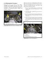
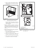
h. From the inside of the enclosure, remove 5
screws to remove the rear (exhaust end) panel.
See Figure 7-3.
tp6196
1. Screws (5 ea.)
1
1
Figure 7-3
Rear Panel Mounting Screw Locations
(viewed from inside the enclosure)
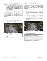
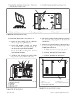
i. From the inside of the enclosure, remove the
remaining screws to remove the non-service
side housing panel.
2. Note
the
alternator
connections
inside
the
controller box for reconnection later. Disconnect
the alternator leads inside the controller box. See
Figure 7-4 or Figure 7-5 and the wiring diagrams in
Section 8.
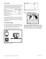
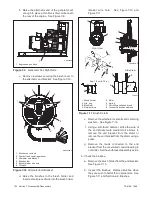
3. Remove the engine exhaust muffler and alternator
heat shield. See Figure 7-6.
a. Disconnect the muffler from the engine exhaust
pipe at the two flange connections.
b. Remove the bolts holding the muffler to the
alternator heat shield and remove the muffler.
c. Remove the bolts securing the heat shield to
the alternator and remove the heat shield.
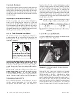
1
GM29253A-F
1. Controller box location
2. Line circuit breaker
3. SCR module
4. Neutral connection terminal L0
Controller Box Top View
4
3
2
2
Figure 7-4
Alternator Connections inside Controller
Box, ADC 2100
Содержание 12RES
Страница 2: ......
Страница 6: ...TP 6196 10 09 6 Notes ...
Страница 34: ...TP 6196 10 09 34 Section 3 Troubleshooting Notes ...
Страница 52: ...TP 6196 10 09 52 Section 4 ADC 2100 and DC 2200 Controllers Notes ...
Страница 72: ...TP 6196 10 09 72 Section 5 ADC RES and DC RET Controller Notes ...
Страница 100: ...TP 6196 10 09 100 Section 6 Component Testing and Adjustment Notes ...
Страница 131: ......


