


TP-6196 10/09
31
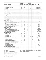
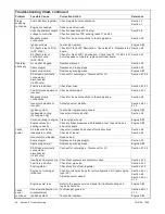
Section 3 Troubleshooting
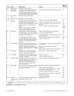
Troubleshooting Chart, continued
Problem
Reference
Corrective Action
Possible Cause
Overheats
Inadequate cooling
Inspect cooling system for air intake obstructions.
Section 2.5
Fuel mixture adjustment
incorrect
Readjust fuel mixture.
Note:
Adjusting the fuel mixture may void the emission
certification.
Section 6.12
Low output
or
excessive
drop in
voltage
Generator overloaded
Reduce load.
—
Incorrect controller
configuration
Check and adjust the controller configuration parameters.
Section 4.5 or
5.5
Incorrect controller
voltage settings
Check and adjust the controller voltage settings.
Section 4.5.3 or
5.6
Alternator or control
system
Perform separate excitation procedure to isolate problem to the
alternator or the control system.
Section 6.2
SCR module
Check wiring and connections to the SCR module.
Check auxiliary winding fuse F1.
Replace SCR module and test voltage.
Section 6.13
Section 6.8
Controller
Check controller settings. Check controller fuse, wiring and
connections.
Before replacing controller, replace SCR module and test
voltage.
Section 4.5 or
5.5
Section 6.8
Rotor (open, grounded,
or shorted windings)
Test and/or replace.
Section 6.4
Stator (open, grounded,
or shorted windings)
Test and/or replace.
Section 6.3
Brush connection
Check for loose brush connections.
Check the resistance through the brushes. Resistance through
the brushes should be low, 0.1--0.2 ohms without meter lead
resistance.
Section 6.6
Low engine speed
causing voltage roll-off
Check system voltage/frequency (Uu) and engine type (Ec)
parameters.
Adjust engine governor speed.
Troubleshoot engine.
Section 4.5 or
5.5
Section 6.9 or
6.10
Engine S/M
Light flicker
Voltage stability (gain)
setting
Check and adjust the voltage stability (gain) setting using the
controller keypad.
Section 4.5.3
High output
voltage
Incorrect controller
configuration
Check and adjust the controller configuration parameters.
Section 4.5 or
5.5
Incorrect controller
voltage settings
Check and adjust the controller voltage settings.
Section 4.5.3
Engine speed too high
Check engine speed using tachometer or frequency meter.
Adjust governor as necessary.
Section 6.9 or
6.10
Loose voltage sensing
connections
Check connections: stator leads 11 and 44 and P15 controller
connection.
Section 8
SCR module
Check wiring and connections to the SCR module.
Check auxiliary winding fuse F1 (lead 55).
Replace SCR module and recheck voltage.
Section 6.8
Section 6.13
Section 6.8
Controller
Check fuses, wiring and connections. Before replacing
controller, replace SCR module and test voltage.
Section 4.9
Содержание 12RES
Страница 2: ......
Страница 6: ...TP 6196 10 09 6 Notes ...
Страница 34: ...TP 6196 10 09 34 Section 3 Troubleshooting Notes ...
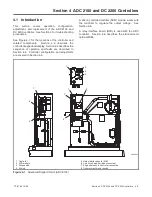
Страница 52: ...TP 6196 10 09 52 Section 4 ADC 2100 and DC 2200 Controllers Notes ...
Страница 72: ...TP 6196 10 09 72 Section 5 ADC RES and DC RET Controller Notes ...
Страница 100: ...TP 6196 10 09 100 Section 6 Component Testing and Adjustment Notes ...
Страница 131: ......


