background image

PREPARATION

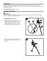
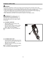
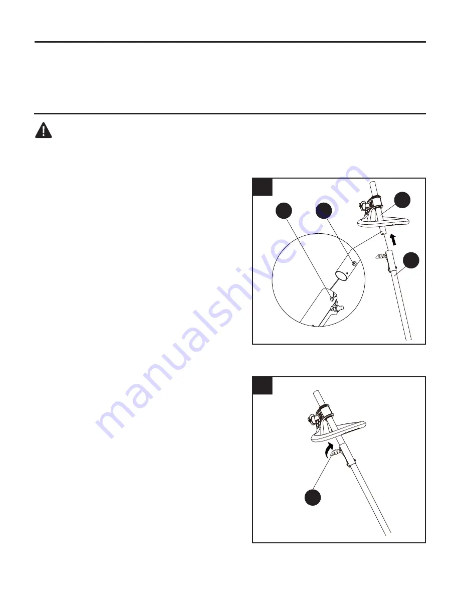
a.      Align the pin (E) on the upper handle 

     assembly (A) with the hole (F) on the lower     

    handle assembly (B). Insert the upper 

    handle assembly into the lower handle 

    assembly until the pin clicks into the hole.

1a

Before beginning assembly of product, make sure all parts are present. Compare parts with 

package contents list and hardware contents list. If any part is missing or damaged, do not attempt to           

assemble the product.

Estimated Assembly Time: 

5 minutes

ASSEMBLY INSTRUCTIONS

WARNING

To prevent accidental starting that could cause serious personal injury, always remove the battery 

pack from the tool when assembling parts.

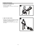
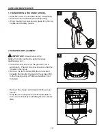
1. ASSEMBLING THE SHAFTS

1b

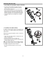
b.  Once the two shafts are secured, turn 

the lock knob (G) clockwise until it is fully    

tightened.

F

E

G

A

B

9

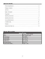
Содержание 0533630

Страница 1: ...30 MODEL KSS 2080A 06 Serial Number Purchase Date Questions problems missing parts Before returning to your retailer call our customer service department at 1 888 3KOBALT 1 888 356 2258 8 a m 8 p m EST Monday Friday AB17435 ATTACH YOUR RECEIPT HERE 1 ...

Страница 2: ... 9 Operating Instructions 11 Care and Maintenance 13 Troubleshooting 16 Warranty 17 Replacement Parts List 18 SPECIFICATIONS Type Cordless battery operated Motor 80 V brushless motor No load speed 1 800 RPM Clearing width 12 in 30 cm Clearing depth 4 in 10 cm Impeller size 11 in 28 cm Discharge distance 20 ft 6 m Weight without battery 16 lbs 7 3 kg 2 ...

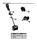
Страница 3: ...PART DESCRIPTION QUANTITY A Upper Handle Assembly 1 B Lower Handle Assembly 1 C Battery 1 D Charger 1 PACKAGE CONTENTS A B C D 3 ...

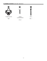
Страница 4: ...HARDWARE CONTENTS not shown actual size AA Fastening Knob Qty 1 BB Screws preassembled Qty 4 CC Bolt Qty 1 4 ...

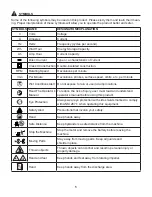
Страница 5: ...ions Alert Do not expose to rain or use in damp locations Read The Operator s Manual To reduce the risk of injury user must read and understand operator s manual before using this product Eye Protection Always wear eye protection with side shields marked to comply with ANSI Z87 1 when operating this equipment Safety Alert Precautions that involve your safety Hand Keep hands away Safe Distance Keep...

Страница 6: ...Stay away from impeller openings at all times Keep face hands and feet away from concealed moving or rotating parts Be attentive when using the power tool Stay alert for holes in the terrain and other hidden hazards or traffic Move up and down slopes when clearing snow Do not go across a slope Use caution when changing direction Do not use this power tool to clear snow from steep slopes Do not ope...

Страница 7: ... boots when operating the power tool Do not operate the equipment when barefoot or wearing open sandals Always wear substantial footwear Operation of the power tool in the hand held position is unsafe except in accordance with the special instructions for such use provided in the operator s manual Keep guards in place and in working order Don t Force Power Tool It will perform better and safer at ...

Страница 8: ... each use Refer to the Maintenance Section in this manual for more information If the labels on the power tool become defaced or start to lift off contact customer service at 1 888 356 2258 Keep these instructions in a safe place for future reference Refer to them often and use them to instruct other users Anyone who uses this power tool must read these instructions carefully Maintain the power to...

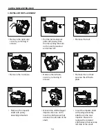
Страница 9: ...nt Compare parts with package contents list and hardware contents list If any part is missing or damaged do not attempt to assemble the product Estimated Assembly Time 5 minutes ASSEMBLY INSTRUCTIONS WARNING To prevent accidental starting that could cause serious personal injury always remove the battery pack from the tool when assembling parts 1 ASSEMBLING THE SHAFTS 1b b Once the two shafts are ...

Страница 10: ...2b TO REMOVE BATTERY IMPORTANT The battery pack is not WARNING Follow these instructions in order to avoid injury and to reduce the risk of electric shock or fire Replace the battery pack or the charger immediately if the battery case or charger cord is damaged Verify that the switch is in the OFF position before inserting or removing the battery pack Verify that the battery pack is removed and th...

Страница 11: ...ngaged before the trigger switch is active Once the trigger switch is engaged release the lock out button Hold the handle and begin to use the snow shovel 1 ADJUSTING THE AUXILIARY HANDLE POSITION Position the front auxiliary handle I onto the upper portion of the shovel section by sliding over the rubber sleeve J Once the front handle is in the desired position slide the bolt CC through the under...

Страница 12: ...he lock out button will pop out and the snow shovel will stop 4 USING THE SNOW SHOVEL Start the snow shovel by following the starting instructions The depth and weight of the snow will determine the forward speed Push the snow shovel forward so that it rides on the scraper 3 4 12 ...

Страница 13: ...d discard it in the proper manner Snap the new scraper into position and attach it to the snow shovel by reinstalling the four screws BB Allow the motor to cool down before transporting Secure the snow shovel while transporting When moving the snow shovel grasp it by the top handle and auxiliary handle 1 TRANSPORTING THE SNOW SHOVEL 1 CARE AND MAINTENANCE 2 SCRAPER REPLACEMENT M BB M 2 IMPORTANT A...

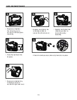
Страница 14: ...emove the nut that secures the left side plate Remove the impellor shaft with pulley assembly attached Discard the old damaged impellor Be sure not to lose the shaft sleeve that secures the left side of the shaft Insert the impellor shaft with pulley assembly attached in the new impellor Be sure to replace the retained shaft sleeve that secures left side of the shaft 3 IMPELLOR REPLACEMENT CARE AN...

Страница 15: ... screws to secure the left side cover Replace and tighten the remaining screws to secure the pulley assembly Place the belt back into its place Place the belt tensioner idler arm back into its place Replace and tighten the remaining screws to secure the right side cover CARE AND MAINTENANCE 3o 3j 3k 3l 3m 3n 15 ...

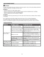
Страница 16: ...tton or trigger switch were not used properly Press and hold the lock out button while holding the lock out button press the switch trigger see page 11 Battery is too cold Remove battery from snow shovel Place battery on charger and allow to charge for 10 minutes Remove from charger and install in snow shovel for use The battery is not fully inserted into the housing Check if the battery is fully ...

Страница 17: ...hase to the place of purchase for a free replacement or refund or call 1 888 3KOBALT 1 888 356 2258 for war ranty service This warranty is void if defects in materials or workmanship or damages result from repairs or alter ations which have been made or attempted by others or the unauthorized use of nonconforming parts the damage is due to normal wear damage is due to abuse including overloading o...

Страница 18: ...ervice department at 1 888 3KOBALT 1 888 356 2258 8 a m 8 p m EST Monday Friday PART DESCRIPTION PART AA Fastening Knob 34113877 1 BB Screw 32205877 CC Bolt 322051410 M Scraper 341041468 DD Belt 329011468 EE Impeller 341031468AC Printed in China AA CC BB M DD EE 18 ...

Отзывы: