ADJUSTMENT
10
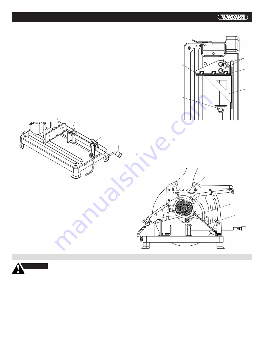
ADJUSTING THE VISE (FIG. G)
NOTE: The vise of your saw is used to secure the workpiece
during cutting operations.
1. Rotate the vise crank (1) counterclockwise to allow
enough room for the workpiece to fit between the vise
clamp (2) and the adjustable fence (3).
2. Position the workpiece between the vise clamp and the
adjustable fence. Turn the vise crank (1) clockwise to
clamp the workpiece securely.
3. The vise incorporates a quick release locking lever (4).
To use the quick release feature, lift up on the quick
release locking lever (4) and slide the vise clamp in or out
to the desired position.
4. When vise clamp is in desired location, flip the quick
release locking lever (4) down to engage the threads with
the threads of the vise. Begin to turn the vise crank (1)
clockwise to secure the workpiece within the vise.
Fig. G
1
4
2
3
ADJUSTING FOR ANGLE CUTTING (FIG. H)
1. Loosen the vise crank and back the vise clamp (3) away
from the adjustable fence (2).
2. Loosen the two bolts (1) of the adjustable fence with the
cutting wheel wrench.
3. Move the adjustable fence (2) to the desired angle
between 0 and 45 degrees.
4. Tighten the two bolts (1).
5. The vise clamp (3) will align itself automatically with the
angle of the workpiece when clamping a workpiece in
position.
NOTE: To check the squareness of the blade to the fence:
CARRYING YOUR CHOP SAW (FIG. I)
The
chop saw can be transported to any workplace
conveniently by:
1. Lowering the cutting arm to its lowest position and
securing in place by attaching the locking chain (1)
to the hook (2), located on the motor housing.
2. Transport the saw using the carrying handle (3) located
above the motor.
1. Loosen the vise crank and back the vise clamp (3)
from the adjustable fence (2).
2. Loosen
the two
bolts (1) on the
adjustable fence
with the cutting
wheel wrench.
3. Lower the cutting
arm down until
the wheel (4) is
below the base.
4. Place a square
(5) against the
wheel and adjust
the fence against
the square.
5. Raise the cutting
arm up and lock
the fence into
position.
Fig. H
5
4
1
2
3
Fig. I
3
2
1
OPERATION
WARNING
Never connect the plug to the power
source outlet until all installations and adjustments
are completed and you have read and understood
the safety and operational instructions.
ON/OFF SWITCH (FIG. J)
The
ON/OFF trigger switch (1) is located on the handle
position of the cutting arm.
1. Turn the chop saw ON by depressing the trigger switch (1).
2. To turn off, release the trigger switch (1).
NOTE: Make the ON/OFF switch childproof. Insert a
padlock or chain with padlock through the hole (3) in the
trigger switch to lock the switch, preventing children and
other unauthorized users from turning the machine on.
LOCK-ON BUTTON (FIG. J)
1.
To
engage the lock-on feature, depress the trigger switch (1),
and simultaneously push in the lock-on button (2) located
on the side of the handle. Release the switch and the tool
will run continuously.
2. To disengage the lock-on feature, depress the trigger
switch and release.
Содержание KN CS-3555R
Страница 1: ...KN CS 3555R Chop saw14 Cortadora para metal 355 6 mm...
Страница 16: ...15 SCHEMATIC KN CS 3555R Chop saw 14 Cortadora para metal 355 6 mm...
Страница 32: ...ESQUEMA 31 KN CS 3555R Chop saw 14 Cortadora para metal 355 6 mm...
Страница 33: ...NOTE NOTAS 32...
Страница 34: ...NOTE NOTAS 33...
Страница 35: ...NOTE NOTAS 34...
Страница 36: ...www knova com mx...


