background image

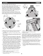
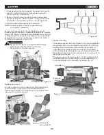
Figura 21

Alimentar

AjUSTES

28

Los rodillos de entrada y de salida están bajo tensión de

resorte y esta tensión debe ser suficiente para alimentar el

abastecimiento uniformemente a través de la cepilladora sin 

deslizamiento, pero no debe ser tan ajustada que cause daño

a la tabla. La tensión debe ser igual en ambos extremos de

cada rodillo.
Para ajustar la tensión del resorte de los rodillos de entrada y 

de salida, gire los tornillos (Figura 22) con una llave

hexagonal. Un giro a la derecha aumenta la tensión en el

resorte de presión. Vea la Figura 23. Un giro a la izquierda

 disminuye la tensión. Ajuste los tornillos en el otro

extremo de los rodillos con el mismo número de vueltas.

Altura del rodillo de entrada, rompedor de viruta

y rodillo de salida

El rodillo de entrada, el rompedor de virutas y el rodillo de

salida se ajustan en fábrica. La relación de altura entre estos

elementos y el cabezal cortador es crucial para un cepillado

preciso y seguro. El rodillo de entrada, el rompedor de viruta

y el rodillo de salida deben colocarse a 0,02” (0,5 mm)

por debajo del círculo de corte.

Tornillos de ajuste

de tensión del resorte

Figura 22

Tornillo de ajuste

de altura

Tuerca de

comprobación

Rodillo

Resorte de presión

Tornillo de presión

Figure 23

Si se necesitan ajustes para el rodillo de entrada, el rompedor

de virutas o el rodillo de salida, deben hacerse con cuidado. 

Utilice los pasos siguientes como ejemplo de procedimiento.
NOTA: Este procedimiento utiliza un calibrador de bloqueo

de fabricación casera y calibradores de espesores, que

deben ser suficientes para la mayoría de las operaciones

de la cepilladora. Sin embargo, si se desean mediciones muy

 precisas, utilice un dispositivo indicador de cuadrante.

Figura 24

0.02” (0.5 mm)

0.02” (0.5 mm)

Rodillo de salida

Mesa

Rodillo de entrada

Rompedor de viruta

Cabezal cortador

Ensamble de corte y rodillos (vista lateral)

Содержание KN CM-15W3

Страница 1: ...KN CM 15W3 Belt and disc sander 4 x6 101 6 mm 914 4 mm Lijadora de banda y disco Closed stand Gabinete cerrado ...

Страница 2: ...the elbows Remove all loose clothing and confine long hair Non slip footwear or anti skid floor strips are recommended Do not wear gloves 8 Wear ear protectors plugs or earmuffs during extended periods of operation 9 Some dust created by power sanding sawing grinding drilling and other construction activities contain chemicals known to cause cancer birth defects or other reproductive harm Some exa...

Страница 3: ... heeded it may result in serious injury or possibly even death CAUTION WARNING 28 Turn off the machine and disconnect from power before cleaning Use a brush or compressed air to remove chips or debris do not use your hands 29 Do not stand on the machine Serious injury could occur if the machine tips over 30 Never leave the machine running unattended Turn the power off and do not leave the machine ...

Страница 4: ...extension table must be leveled with the main table Place a straight edge such as a jointed board across both tables Remove the screws holding the planer to the pallet and use a forklift or hoist to lift the planer off the pallet Forks and straps should always be placed under the four lifting handles when lifting this machine Figure 3 The lifting handles can be pushed back in when not in use The p...

Страница 5: ...se the planer Belts often stretch during this trial period If they require tightening proceed as follows 1 Remove the belt guard and the rear panel 2 Loosen the bottom nut on the motor adjustment screw 3 Turn the top nut on the adjustment screw to lower the motor plate which will increase the belt tension 4 Proper tension is achieved when there is slight deflect on in the belt midway between the p...

Страница 6: ... front and rear rollers are the same And the table rollers must always be set parallel to the table Cutterhead Although your planer was carefully adjusted at the factory it should be checked before being put into operation Any inaccuracies due to rough handling in transit can be corrected by following the directions in this manual To check the adjustments you will need feeler gauges and a home mad...

Страница 7: ...ble Parallel to Cutterhead The work table is set parallel to the cutterhead at the factory and no further adjustment should be necessary If your machine is planing a taper first check to see if the knives are set properly in the cutterhead Then check to see if the work table is set parallel to the cutterhead Proceed as follows 1 Disconnect machine from power source 2 Place the gauge block Figure 1...

Страница 8: ...and Outfeed Roller Spring Tension The infeed roller B Figure 21 and outfeed roller E Figure 21 are those parts of your planer that feed the stock while it is being planed The infeed and outfeed rollers are under spring tension and this tension must be sufficient to feed the stock uniformly through the planer without slipping but should not be so tight that it causes damage to the board The tension...

Страница 9: ...til the knife just touches the feeler gauge when the knife is at its lowest point Do not move the work table any farther until the outfeed roller is adjusted 5 Remove the feeler gauge and move the gauge block F Figure 25 under one end of the outfeed roller The bottom of the outfeed roller should just touch the top of the gauge block If an adjustment to the outfeed roller is necessary loosen the lo...

Страница 10: ...tension at all times To gain access to the chain and sprockets for example when performing maintenance proceed as follows 1 You may find it easier to remove the sprocket guard by first removing the handwheel from the machine though this is not mandatory 2 Remove the socket head cap screw from the center of the cover using a 6mm hex wrench Remove the left triangular back plate 2 screws using a 10mm...

Страница 11: ... paste wax on exposed steel and cast iron surfaces The wax provides a layer of protection as well as reducing friction between lumber and the table making cuts faster and smoother Avoid any wax that contains silicone or other synthetic ingredients These materials can find their way into lumber and can make staining and finishing difficult Another option is talcum powder applied with a blackboard e...

Страница 12: ...face of feed roller is clogged Knives are worn Cutterhead not level with bed Inadequate tension Sprockets misaligned Sprockets worn Adjust chain tension Align sprockets Replace sprockets Depth of cut scale incorrect Adjust depth of cut scale Adjust rollers to proper height Support long boards with extension tables Adjust feed roller tension Replace knives Butt end to end each piece of stock as the...

Страница 13: ...aner including motor connections verifying the tightness of each Look for any signs of electrical arcing which is a sure indicator of loose connections or circuit overload If electric motor is suspect you have two options Have a qualified electrician test the motor for function or remove the motor and take it to a qualified electric motor repair shop and have it tested If the on off switch is susp...

Страница 14: ... X 10 4 44 REAR GEARBOX COVER PLATE L 1 45 CAP SCREW M5 8 X 10 4 46 FLAT WASHER 5MM 2 PLANER HEADSTOCK PARTS LIST 13 D e s c r i p t i o n Qty REF D e s c r i p t i o n Qty REF 47 SCALE BRACKET 1 48 DEPTH LIMITER 1 49 FLAT HD SCR M5 8 X 10 2 50 KEY 5 X 5 X 15 2 51 SET SCREW M8 1 25 X 12 1 52 PULLEY SPACER 1 53 HEX NUT M8 1 25 2 54 LOCK WASHER 8MM 2 55 FLAT WASHER 8MM 2 56 STANDOFF HEX M8 1 25 X 10...

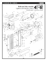
Страница 15: ...DIAGRAM PLANER HEADSTOCK 14 914 4 mm Belt and disc sander 4 x6 101 6 mm Lijadora de banda y disco Closed stand Gabinete cerrado KN CM 15W3 ...

Страница 16: ...E EXTENSION WING 2 D e s c r i p t i o n Qty REF D e s c r i p t i o n Qty REF 111 SET SCREW M8 1 25 X 12 4 112 LOCKING ROD 2 113 LOCK SLEEVE 2 114 BALL BEARING 6201ZZ 4 115 BED ROLLER 2 116 LOCK WASHER 6MM 8 117 CAP SCREW M6 1 X 20 8 118 FLAT WASHER 8MM 4 119 LOCK WASHER 8MM 4 120 CAP SCREW M8 1 25 X 25 4 DIAGRAM PLANER TABLE 914 4 mm Belt and disc sander 4 x6 101 6 mm Lijadora de banda y disco C...

Страница 17: ...DSCREW 1 227 KEY 4 X 4 X 12 5 228 BALL BEARING 6201ZZ 1 229 BUSHING 1 230 GEAR 20T 1 201 BASE 1 202 SCALE COLUMN 1 203 COLUMN 3 204 LEADSCREW NUT 4 205 SECONDARY LEADSCREW 3 206 EXT RETAINING RING 20MM 4 207 HEX NUT M8 1 25 4 208 CHAIN TENSION BRACKET 1 209 GEAR SHAFT 1 210 GEAR 10T 1 211 EXT RETAINING RING 12MM 2 212 CHAIN 081 1 X 134 1 213 FENDER WASHER 8MM 2 214 LOCK WASHER 8MM 6 215 CAP SCREW ...

Страница 18: ...FTING SHAFT 1 332 LOCK WASHER 6MM 1 333 O RING 9 X 1 8 2 334 ROLL PIN 5 X 25 2 301 GEARBOX 1 302 OIL SEAL 25 X 40 X 7 1 303 BALL BEARING 6204ZZ 2 304 GEAR 15T 1 305 CAP SCREW M6 1 X 25 LH 1 306 FENDER WASHER 6MM 1 307 FLANGE BOLT M6 1 X 12 2 308 BALL BEARING 6201ZZ 5 309 GEAR 47T 1 310 GEARED SHAFT 18T 1 311 KEY 5 X 5 X 12 1 312 GEAR 71T 1 313 KEY 5 X 5 X 10 1 314 COMBO GEAR 22T 18T 1 315 O RING 1...

Страница 19: ... LOWER 1 424 HEX NUT M8 1 25 1 425 T KNOB M8 1 25 70 DIA X 48L 1 401 SPROCKET 32T 1 402 FENDER WASHER 6MM 5 403 CAP SCREW M6 1 X 16 3 404 FLAT WASHER 10MM 1 405 CHAIN TENSIONER 2 406 CHAIN TENSIONER SHAFT 1 407 CHAIN TENSIONER BRACKET UPPER 1 408 CHAIN 06B 1 X 48 1 409 SPROCKET 13T 1 410 SHOULDER BOLT M8 1 25 X 16 12 X 3 5 1 411 CAP SCREW M6 1 X 10 2 412 KEY 5 X 5 X 15 1 413 DOUBLE STRAND SPROCKET...

Страница 20: ...OT 2 534 HEX NUT M10 1 5 2 535 REAR WHEEL 2 536 REAR WHEEL BUSHING 2 537 CAP SCREW M8 1 25 X 60 2 538 STRAIN RELIEF TYPE 3 M20 1 5 1 539 MOTOR CORD 1 501 STAND 1 502 BACK COVER 1 503 PHLP HD SCR M6 1 X 16 1 504 MOTOR 1 504 1 MOTOR FAN COVER 1 504 2 CAPACITOR COVER 1 504 3 MOTOR JUNCTION BOX 1 504 4 MOTOR FAN 1 504 5 START CAPACITOR 1 504 6 RUNNING CAPACITOR 1 504 7 CONTACT PLATE 1 504 8 CENTRIFUGA...

Страница 21: ...20 DIAGRAM PLANER cabinet 914 4 mm Belt and disc sander 4 x6 101 6 mm Lijadora de banda y disco Closed stand Gabinete cerrado KN CM 15W3 ...

Страница 22: ...sistentes a los impactos no son gafas de seguridad 7 Antes de operar esta cepilladora quítese la corbata anillos relojes y otras joyas arremangue las mangas por encima de los codos Quítese toda ropa suelta y sujétese el pelo largo Se recomienda el uso de calzado antiderrapante No use guantes 8 Use protectores auriculares tapones u orejeras durante períodos prolongados de operación 9 Algunos polvos...

Страница 23: ...mpias para el mejor y más seguro rendimiento Siga las instrucciones para lubricar y cambiar los accesorios 27 Asegúrese que la pieza de trabajo esté firmemente fijada o sujeta a la mesa Nunca use su mano para sostener la pieza de trabajo 28 Apague la máquina y desconéctela de la corriente eléctrica antes de limpiarla Use un cepillo o aire comprimido para quitar virutas o escombros no use sus manos...

Страница 24: ...as horquillas y las correas deben colocarse siempre debajo de los cuatro mangos de elevación al levantar la máquina Figura 3 Los mangos de elevación pueden ser empujadas hacia atrás cuando no estén en uso Tenga cuidado al limpiar alrededor del área del cabezal cortador las cuchillas son extremadamente afiladas Figura 3 Figura 4 Mangos elevadores Figura 2 Ensamblaje La cepilladora debe ser operada ...

Страница 25: ...xagonal M6 x 12 A Figura 8 Se recomienda encarecidamente que utilice un sistema de recolección de polvo con esta cepilladora Si no está utilizando un sistema de recolección de polvo no acople la tolva extractora a la cepilladora ya que la acumulación de aserrín dentro de la tolva puede crear un peligro para la seguridad o eventualmente provocar un atasco del sistema de rodillos en el cabezal corta...

Страница 26: ...estar en posición baja NOTA Al subir el rodillo por encima de la mesa el rango es de cero a 0 06 Figura 15 Los rodillos de mesa se ajustan en fábrica para un cepillado medio y están paralelos a la superficie de la mesa Si desea ajustar los rodillos de mesa más arriba o más abajo proceda de la siguiente manera 1 Desconecte la máquina de la fuente de alimentación 2 Coloque una regla recta a través d...

Страница 27: ...e la cuchilla toque las almohadillas de referencia centrales en el calibrador Sostenga el calibrador hacia abajo y apriete los pernos para asegurar la cuchilla en su lugar Repita para las otras 2 cuchillas b Utilice los tornillos de sujeción para ajustar la altura de la cuchilla Utilice una llave Allen para girar los tornillos para subir o bajar la cuchilla según sea necesario hasta la posición id...

Страница 28: ...ra 20 que le permitirá mover el conjunto del piñón intermedio C Figura 20 lo suficiente como para liberar la tensión en la cadena Conociendo los rodillos transmisores de la cepilladora Figura 21 A Dedos anti retroceso B Rodillo de alimentación C Rompedor de viruta D Cabezal cortador E Rodillo de salida Dedos anti retroceso Los dedos anti retroceso A Figura 21 son una importante característica de s...

Страница 29: ...en fábrica La relación de altura entre estos elementos y el cabezal cortador es crucial para un cepillado preciso y seguro El rodillo de entrada el rompedor de viruta y el rodillo de salida deben colocarse a 0 02 0 5 mm por debajo del círculo de corte Tornillos de ajuste de tensión del resorte Figura 22 Tornillo de ajuste de altura Tuerca de comprobación Rodillo Resorte de presión Tornillo de pres...

Страница 30: ...odillos de alimentación están enganchados giran para alimentar el material Los rodillos de alimentación se ralentizan automáticamente cuando la máquina está bajo carga pesada para un mejor cepillado en todas las condiciones Los rodillos de alimentación son accionados por cadenas y piñones véase la figura 28 que toman energía directamente desde el cabezal cortador a través de la caja de engranajes ...

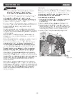
Страница 31: ...illos en la parte superior de la máquina sirven como un apoyo conveniente para el abastecimiento Ellos ahorran tiempo y movimiento para el operador como devolución al lado de entrada No intente cambiar la velocidad de alimentación mientras el material pasa por la máquina Puede dañar la caja de engranes PRECAUCION Figura 28 Tensor Figura 29 Remover la placa posterior Espesor del corte La escala de ...

Страница 32: ... borrador de pizarra frotado vigorosamente una vez por semana esto llenará los poros de fundición y formará una barrera contra la humedad Este método proporciona una capa en la mesa que permite que el óxido se limpie fácilmente de la superficie Importante también es el hecho que el polvo de talco no mancha la madera Otra opción es el polvo de talco aplicado con un borrador de pizarra frotado vigor...

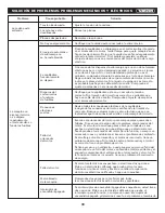
Страница 33: ...lando La superficie del rodillo de alimentación está obstruida Las cuchillas están desgastadas Cabezal cortador no nivelado con la cama Profundidad de la escala de corte incorrecta Ajuste la profundidad de la escala de corte Ajuste los rodillos a la altura adecuada Soporte las tablas largas con las mesas de extensión Ajuste la tensión del rodillo de alimentación Reemplace las cuchillas Terminar de...

Страница 34: ...e cualquier signo de arco eléctrico que sea un indicador seguro de conexiones sueltas o sobrecarga del circuito Si el motor eléctrico es sospechoso usted tiene dos opciones Pida a un electricista calificado que pruebe el motor para funcionar o retire el motor y llévelo a un taller de reparación de motores eléctricos calificado y haga que lo prueben Si el interruptor de encendido apagado es sospech...

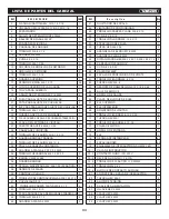
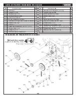
Страница 35: ...5 8 X 10 6 43 TORNILLO M6 1 X 10 4 44 PLACA GUARDA CAJA DE ENGRANES TRASERA I 1 45 TORNILLO M5 8 X 10 4 46 ARANDELA PLANA 5 MM 2 LISTA DE PARTES DEL CABEZAL 34 D E S C R I P C I O N CANT REF D e s c r i p t i o n Qty REF 47 SUJETADOR DE ESCALA 1 48 LIMITADOR DE PROFUNDIDAD 1 49 TORNILLOS CABEZA PLANA M5 8 X 10 2 50 CUÑA 5 X 5 X 15 2 51 TORNILLO FIJADOR M8 1 25 X 12 1 52 ESPACIADOR DE POLEA 1 53 TU...

Страница 36: ...DIAGRAMA DEL CABEZAL 35 914 4 mm Belt and disc sander 4 x6 101 6 mm Lijadora de banda y disco Closed stand Gabinete cerrado KN CM 15W3 ...

Страница 37: ...ENSIÓN DE MESA 2 D E S C R I P C I O N CANT REF D E S C R I P C I O N CANT REF 111 TORNILLO FIJADOR M8 1 25 X 12 4 112 BARRA DE BLOQUEO 2 113 MANGUITO DE BLOQUEO 2 114 BALERO DE BOLAS 6201ZZ 4 115 RODILLO DE CAMA 2 116 ARANDELA DE BLOQUEO 6 MM 8 117 TORNILLOS M6 1 X 20 8 118 ARADELA PLANA 8 MM 4 119 ARANDELA DE BLOQUEO 8 MM 4 120 TORNILLO M8 1 25 X 25 4 DIAGRAMA DE LA MESA 914 4 mm Belt and disc s...

Страница 38: ... 227 CUÑA 4 X 4 X 12 5 228 BALERO DE BOLAS 6201ZZ 1 229 BUJE 1 230 ENGRANE 10 T 1 201 BASE 1 202 COLUMNA DE ESCALA 1 203 COLUMNA 3 204 TUERCA DE HUSILLO 4 205 HUSILLO SECUNDARIO 3 206 ANILLO DE RETENCIÓN EXT 20 MM 4 207 TUERCA HEX M8 1 25 4 208 SOPORTE DE TENSIÓN DE CADENA 1 209 EJE DE ENGRANE 1 210 ENGRANE 10 T 1 211 ANILLO DE RETENCIÓN EXT 12 MM 2 212 CADENA 081 1 X 134 1 213 ARANDELA 8 MM 2 214...

Страница 39: ...E DE DESPLAZAMIENTO 1 332 ARANDELA DE BLOQUEO 6 MM 1 333 O RING 9 X 1 8 2 334 PASADOR 5 X 25 2 301 CAJA DE ENGRANES 1 302 SELLO DE ACEITE 25 X 40 X 7 1 303 BALERO DE BOLAS 6204ZZ 2 304 ENGRANE 15 T 1 305 TORNILLO M6 1 X 25 LH 1 306 ARANDELA 6 MM 1 307 PERNO DE BRIDA M6 1 X 12 2 308 BALERO DE BOLAS 6201ZZ 5 309 ENGRANE 47 T 1 310 EJE DE ENGRANE 18 T 1 311 CUÑA 5 X 5 X 12 1 312 ENGRANE 71 T 1 313 CU...

Страница 40: ... DE CADENA INFERIOR 1 424 TUERCA HEX M8 1 25 1 425 PERILLA T M8 1 25 70 DIA X 48L 1 401 PIÑÓN 32 T 1 402 ARANDELA 6 MM 5 403 TORNILLO M6 1 X 16 3 404 ROLDANA PLANA 10 MM 1 405 TENSOR DE CADENA 2 406 EJE DE TENSOR DE CADENA 1 407 SOPORTE DE TENSOR DE CADENA SUPERIOR 1 408 CADENA 06B 1 X 48 1 409 PIÑÓN 13 T 1 410 PERNO DE HOMBRO M8 1 25 X 16 12 X 3 5 1 411 TORNILLO M6 1 X 10 2 412 CUÑA 5 X 5 X 15 1 ...

Страница 41: ...RA 2 536 BUJE DE RUEDA TRASERA 2 537 TORNILLO M8 1 25 X 60 2 538 ALIVIO DE TENSIÓN TIPO 3 M20 1 5 1 539 CABLE DE MOTOR 1 501 GABINETE 1 502 CUBIERTA POSTERIOR 1 503 TORNILLO PHILLIPS M6 1 X 16 1 504 MOTOR 1 504 1 CUBIERTA DE VENTILADOR DE MOTOR 1 504 2 CUBIERTA DE CAPACITOR 1 504 3 CAJA DE EMPALME DE MOTOR 1 504 4 VENTILADOR DE MOTOR 1 504 5 CAPACITOR DE ARRANQUE 1 504 6 CAPACITOR DE MARCHA 1 504 ...

Страница 42: ...41 DIAGRAMA del Gabinete 914 4 mm Belt and disc sander 4 x6 101 6 mm Lijadora de banda y disco Closed stand Gabinete cerrado KN CM 15W3 ...

Страница 43: ...42 NOTES NOTAS ...

Страница 44: ...www knova com mx ...

Отзывы: