TEMON 4-C
Doc. N°
MO-0368-ING
Microener. - Copyright 2010
2.1
Date
01.12.2008
Rev.
0
Pag.
10
of
14
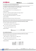
9.10 - Selection data bit, parity and stop bit
NOTE: This
set haven’t mean for the models without the
serial output
RS485 option installed.
This phase is indicated on displays where there is
The type of parity on displays T1-T2 ; number of data bit and stop bit on display T3-T4.
With
and
keys to select the set choice.
Confirm with ENTER.
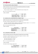
9.11 - Selection of the channel linked to the analogical output
NOTE: This set haven’t mean for the models without the analogical output option installed.
This phase is indicated on displays where there is an on displays T1-T2,
the measure of the linked channel on displays T3-T4 (CH 1/2/3/4 for measure channel 1 / 2 / 3 / 4, all to link
the output on the measure channel with the highest temperature).
With
and
keys to select the set choice.
Confirm with ENTER.
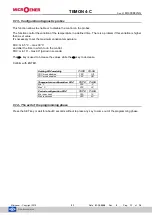
9.12 - Configuration of output signal
NOTE: This set haven’t mean for the models without the analogical output option installed.
In this phase it’s possible to program one of the two type of signal: 0 ÷ 20 mA or 4 ÷ 20 mA.
This phase is indicated on displays where there is
an0 -20 to set the output as 0 ÷ 20 mA or
an4 -20 to set the output as 4 ÷ 20 mA.
With
and
keys to select the options.
Confirm with ENTER.
The maximum load for analogue output is 400
.
Set
T1-T2
T3-T4
No parity / 8 data bit
– 1stop bit
NO
8-1
No parity / 8 data bit
– 2stop bit
NO
8-2
Even parity / 8 data bit
– 1stop bit
EVE
8-1
Odd parity / 8 data bit
– 1stop bit
ODD
8-1
Linked channel
T1-T2
T3-T4
Channel with the highest temperature
AN
all
Measure channel CH 1
AN
ch1
Measure channel CH 2
AN
ch2
Measure channel CH 3
AN
ch3
Measure channel CH 4
AN
ch4
Signal configuration
T1-T2
T3-T4
Output proportionally 0
– 20 mA
AN 0
-20
Output proportionally 4
– 20 mA
AN 4
-20


