9
Knorr-Bremse Group
PD-203-360
Doc. No. Y250908 (EN - Rev. 001)
September 2016
The information contained herein is subject to alteration without notice and therefore may not be the latest release. Please check our website www.knorr-bremseCVS.com for the latest update or contact your local Knorr-Bremse representative.
The figurative mark “K” and the trademarks KNORR and KNORR-BREMSE are registered in the name of Knorr-Bremse AG. Additional terms and conditions apply; please refer to our website knorr-bremseCVS.com for full Disclaimer.
Note: If service work is carried out on a vehicle based on information provided herein, it is the responsibility of the workshop to ensure the vehicle is fully tested and in full
functional order before the vehicle is returned into service. Knorr-Bremse accepts no liability for problems caused as a result of appropriate tests not being carried out.
Copyright © Knorr-Bremse AG - all rights reserved, including industrial property rights applications. Knorr-Bremse AG retains any power of disposal, such as for copying and transferring.
Knorr-Bremse Systeme für Nutzfahrzeuge GmbH . Moosacher Straße 80 . 80809 Munich . Germany . Tel: +49 89 3547-0 . Fax: +49 89 3547-2767 . www.knorr-bremse.com . www.knorr-bremseCVS.com
KB4TA/KB4TA D System Components
C o m m e r c i a l V e h i c l e S y s t e m s
Wheel Speed Sensor
Function:
The wheel speed sensor is mounted, using a spring-
loaded bush, in a housing on the axle in such a position
that the end of the sensor is as close as possible to
the teeth of the sensing ring. The wheel speed sensor
contains an internal permanent magnet whose magnetic
field extends a short distance beyond the end of the
sensor case. A coil is wrapped around a soft iron core,
which is attached to the magnet. This coil is connected
to the output cable.
When a wheel rotates, the teeth of the sensing ring pass
in turn through the magnetic field of the sensor magnet
and disturb the field thereby creating an induced
voltage in the sensor coil. This voltage is monitored by the
KB4TA/KB4TA D module via the output cable. The
voltage generated takes the form of a sine wave with
both the voltage and frequency increasing as the
rotational speed of the wheel increases. The module
requires a minimum voltage before it recognises the
signal from the wheel speed sensor and thereafter it
uses the frequency of the signal to monitor the rotational
speed of the wheel. The voltage generated by the coil is
dependent not only on the rotational speed of the wheel
but also on the gap between the end of the wheel speed
sensor and the teeth of the sensing ring: the larger the
gap the lower the generated voltage. It is important,
therefore, that the gap is kept as small as possible to
ensure that sufficient voltage is generated to maintain
low speed ABS performance.
Technical data:
Operating temperature range:
• Speed sensor: . . . . . . . . . . . . . . -40 °C to +160 °C
• Cable: . . . . . . . . . . . . . . . . . . . . -40 °C to +180 °C
• Plug: . . . . . . . . . . . . . . . . . . . . . -40 °C to +80 °C
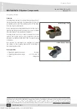
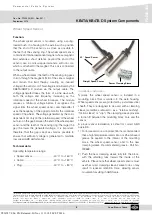
90 ° Speed Sensor
Straight Speed Sensor
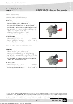
Sensor Clamping Sleeve
Installation instruction
Typically, the wheel speed sensor is installed in a
mounting block that is welded to the axle housing.
Wheel speed sensors are protected by a stainless steel
sheath. They are designed to be used with a clamping
sleeve (sometimes referred to as a “retainer bushing”,
“friction sleeve” or “clip”). The clamping sleeve provides
a friction fit between the mounting block bore and the
sensor.
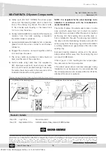
A proper sensor installation is critical for correct ABS
operation.
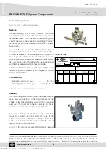
1) For increased corrosion protection it is recommended
that a high temperature rated silicon or lithium based
grease be applied to the interior of the mounting
block, the wheel speed sensor, and to the new
clamping sleeve. Recommended grease - Part No.
I
90693.
2) Push the new clamping sleeve fully into the block,
with the retaining tabs toward the inside of the
vehicle. Please note that wheel speed sensors must
use the correct clamping sleeve. Failure to do so may
result in reduced retention force, allowing sensor
movement resulting in ABS failure.
Y026787: 006: EN: Released: Fri Nov 11 11:18:50 CET 2016:


