background image

Diaphragm liquid pump NF 1.25


Servicing 

KNF Flodos AG


BA_NF1.25_EN_03_163242 

Translation of Original Operating and Installation Instructions, English


17 

Disassemble pump head 

  Undo the four head screws (

1

) using a Torx screwdriver T6 

  Remove the resonating diaphragm (

3

) from the connecting 

plate (

4

). 

Disassemble pump head 

  Remove both anchor valves (

7

) from the intermediate plate (

9

and the connecting plate (

4

  Remove the two anchor valve seals (

6

) from the intermediate 

plate (

9

  Undo the diaphragm (

10

) by means of the head plate (

2

). Make 

sure that no washers (

11

) fall into the housing. 

We recommend replacing the diaphragm (

10

). 

Cleaning the parts 

  Clean the anchor valves (

7

), the anchor valve seals (

6

) and the 

diaphragm (

10

) with a cloth and then blow off with compressed 

air. 

  Blow off the intermediate plate (

9

), connecting plate (

4

) and 

head plate (

2

) with compressed air 

Mounting the diaphragm 

  Screw diaphragm (

10

) with washer (

11

) into connecting rod 

and tighten firmly. Make sure that no washers (

8

) fall into the 

pump housing. 

  Use the head plate (

2

) to carefully tighten the diaphragm. 

Mounting the valves and seals 

 Insert the seals (

6

) in the connecting plate (

4

). 

 Insert the anchor valves (

7

) in the intermediate plate (

9

) and 

the connecting plate (

4

). 

Mounting the pump head 

 Insert the intermediate plate (

9

). 

ATTENTION: Make sure that the orientation is correct so that 
the connections point in the right direction! 
A pin and hole system prevents incorrect assembly. 

 Place the connecting plate (

4

) on top of the intermediate plate 

(

9

 Place head plate (

2

) on connecting plate (

4

) and secure using 

the 4 head screws (

1

8.3.  Replacing diaphragms, valves and seals 

Same procedure as in Chapter 8.2, "Cleaning", except that instead 
of cleaning the diaphragm (

10

), anchor valves (

7

) and seals (

6

), 

these components must be replaced. 


Fig. 10 


1


Head screws 

2


Head plate 

3


Resonating diaphragm 

4


Connecting plate 

5


Clamp ring 

6


Anchor valve seal 

7


Anchor valve 

8


Union nut 

9


Intermediate plate 

10

  Diaphragm 

11 

Washer 


Содержание NF 1.25 DC

Страница 1: ...de is a coun try specific designation with no technical relevance Contents Page 1 About this document 2 2 Use 3 3 Safety 4 4 Technical data 6 5 Assembly and function 9 6 Installation and connection 10...

Страница 2: ...ial danger It also indicates the possible consequences of failure to observe the warning The signal word e g Warn ing indicates the level of danger Here you will see actions for avoiding the danger an...

Страница 3: ...pecific application case Before using a medium check the compatibility of the materials of the pump head pump housing diaphragm and valves with the medium The temperature of the medium must lie within...

Страница 4: ...d understood the Oper ating and Installation Instructions and in particular the Safety chapter Always ensure adherence to all pertinent accident prevention and safety regulations when working on and o...

Страница 5: ...as not ready for use Partly completed machinery may not be commissioned until such time as it has been determined that the machine in which the partly completed machinery is to be assem bled conforms...

Страница 6: ...M Diaphragm PTFE coated Resonating diaphragm FFKM Tab 3 1 according to DIN ISO 1629 and 1043 1 Pump head Fig 1 comprises an intermediate plate and a connecting plate Hydraulic ratings Parameter Value...

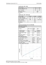
Страница 7: ...wer consumption W 5 8 6 2 7 0 Max I load A 0 48 0 26 0 53 0 25 Protection class IP50 Weight g 185 Tab 7 Electrical specifications for motor DCB 4B Electrical connections Lead assignment Function Wire...

Страница 8: ...high V 2 8 Output level low V 0 5 Tab 8 In the case of type NF 1 25 DCB 4B the supply voltage is not designed for operation with pulse width modulated voltages PWM It is permissible to actuate the co...

Страница 9: ...alve 2 Inlet valve 3 Working chamber 4 Diaphragm 5 Eccentric 6 Connecting rod 7 Pump drive Fig 2 Pump assembly Diaphragm liquid pumps are based on reciprocating displacement pump technology The elasti...

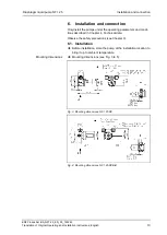
Страница 10: ...ly install the pumps under the operating parameters and condi tions described in Chapter 4 Technical data Observe the safety precautions see Chapter 3 6 1 Installation Before installation store the pu...

Страница 11: ...lla tion position For maximum precision and rapid venting install pump as shown in the illustration Fig 5 6 2 Electrical connection Only have the pump connected by an authorized specialist Only have t...

Страница 12: ...the maximum operating pressure of the pump see Chapter 4 Only use hoses that are sufficiently chemically resistant to the liquids being pumped 6 3 1 Connecting the pump Arrows on the pump head indicat...

Страница 13: ...he pump For further information contact your KNF technical adviser tele phone number see first page If the pump stops running restore the system to normal at mospheric pressure For pumps with thermal...

Страница 14: ...tion check for the pres ence of pressure or vacuum before restarting For more specific information contact your KNF technical adviser Switching off the pump KNF recommends If transferring aggressive l...

Страница 15: ...liquid pump NF 1 25 Operation KNF Flodos AG BA_NF1 25_EN_03_163242 Translation of Original Operating and Installation Instructions English 15 Fig 9 Flow rate of pump NF 1 25 DCB 4B depending on contro...

Страница 16: ...ctive clothing if necessary e g pro tective gloves Flush the pump with a neutral liquid and pump empty 8 2 1 Flushing the pump If transferring aggressive media KNF recommends flushing the pump with a...

Страница 17: ...ew diaphragm 10 with washer 11 into connecting rod and tighten firmly Make sure that no washers 8 fall into the pump housing Use the head plate 2 to carefully tighten the diaphragm Mounting the valves...

Страница 18: ...anchor valves and seals see Chapter 8 3 Tab 12 Pump is not priming Cause Fault remedy Suction side of pump not con nected Connect the suction side of the pump Liquid in the priming container is too l...

Страница 19: ...n the pump Clean the pump head install suction side filter if required see Chapter 8 2 Viscosity of the transferred medium is too high Contact KNF Incorrect interchange of pres sure and suction line c...

Страница 20: ...ondition that the customer provides certification of the transferred media and the cleaning of the pump decontamination declaration In order to send a product back use the decontamination declaration...

Страница 21: ...Diaphragm liquid pump NF 1 25 For your notes KNF Flodos AG BA_NF1 25_EN_03_163242 Translation of Original Operating and Installation Instructions English 21...

Страница 22: ...Diaphragm liquid pump NF 1 25 For your notes KNF Flodos AG BA_NF1 25_EN_03_163242 Translation of Original Operating and Installation Instructions English 22...

Страница 23: ...Diaphragm liquid pump NF 1 25 For your notes KNF Flodos AG BA_NF1 25_EN_03_163242 Translation of Original Operating and Installation Instructions English 23...

Страница 24: ...KNF worldwide Please find your local KNF partners at www knf com...

Отзывы: