2
Introduction
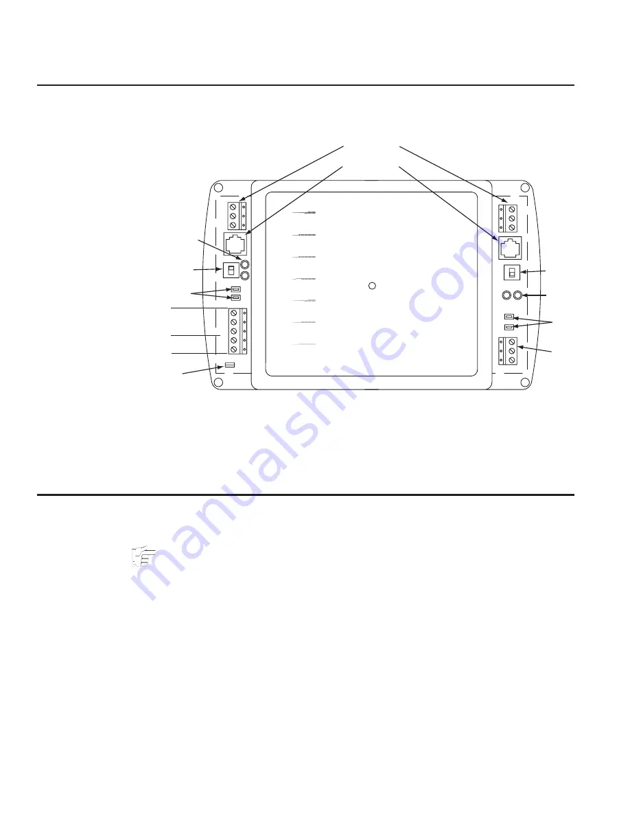
This section provides an overview of the KMD-5540 CommTalk Protocol Interface.
Illustration 1 shows the major components and their locations.
Installation
This section provides important instructions and guidelines for installing the
KMD-5540. Carefully review this information prior to attempting installation.
Note:
The actual configuration of the interface will depend on the model. KMDigital
connections are made to the left side of the interface and third-party equipment is
connected on the right side.
Mounting
Use the four mounting holes to securely mount the interface inside a UL-approved
Enclosed Energy Management Equipment Panel or other suitable protective enclo-
sure. See
Illustration 2—Mounting Hole Locations on page 3
.
Illustration 1—Controller Components
GND
~
GND
A1
B1
LAMPS
RDY
COM
PWR
24VAC
GND
TX1
RX1
GND
A2
B2
COM
RDY
LAMPS
GND
RX2
TX2
OFF
ON
ON
OFF
____ KMC CONTROLS
CommTalk
Protocol
Interface
KMD-5540
KMC
KMDIGITAL
KMC
KMDIGITAL
KMDIGITAL
KMDIGITAL
KMDIGITAL
KMDIGITAL
KMC
KMC
KMC
KMC
KMDIGITAL
KMC
KMC
RS-232 Terminals
RJ-12 Connectors
Network
Switch
Isolation
Lamps
Status
LEDs
Network
Switch
Isolation
Lamps
Status
LEDs
RS-485
Conn.
Power
Power
Jumper
RS-485
Conn.


