Operating Instructions KLAROconnect
Status 06/2022
KLARO GmbH
Page 10/21
Interface description
5
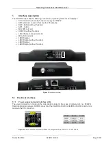
The KLAROconnect has the following connections, operating elements and displays:
•
X6 connector 6-pin (male) for power supply and RS232
•
SMA antenna connector (female) for LTE antenna
•
SW2 - Button (without function)
•
SW1 - button
•
Mini SIM card slot
•
USB 2.0 (without function)
•
LAN Ethernet connection RJ45
•
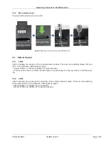
Micro SD card slot
•
LED6 Display
•
LED1 Display (without function)
•
LED5 Display
•
LED2 Display (without function)
Figure 5:
Interface overview
5.1 Electrical interfaces
5.1.1 Power supply and serial interface (-X6)
The power connection is made via the data cable included in the scope of delivery (art. no.: 982223).
Data transmission between KLAROconnect and the KLAROcontrol.S or
KLAROcotrol
. M control unit is
made via the X6 connection.
Pin #1
Pin #3
Pin #5
GND COM_Tx 24V
GND COM_Rx GND
Pin #2 Pin #4 Pin #6
Figure 6
Power connection and serial interface -X6, assignment 6-pin WAGO 713-1423/107-000
1 3 5
2 4 6
-X6
Operating Instructions KLAROconnect
Status 06/2022
KLARO GmbH
Page 11/21
5.1.2 USB 2.0
Connection: USB 2.0 Type A
Has no function.
5.1.3 LAN Ethernet connection
Connection: RJ45
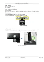
Both control LEDs serve as a practical means of determining the operating mode of the LAN trans-
ceiver.
The LED1 (right) indicates the status of the transmission. If this LED1 flashes or flickers, then data is
being transmitted.
LED2 (left) lights up when there is a connection to a network.
LED1 is the right-hand LED, LED2 the left-hand LED in the picture.
Figure 7
LAN connection
5.1.4 SMA antenna connection
Connection: SMA
The antenna should be screwed on hand-tight without tools. Please only use the LTE antenna includ-
ed in the scope of delivery, other antennas may only be used after consultation with KLARO.
Figure 8:
Attach the LTE antenna
LED2
LED1
Содержание 970716
Страница 23: ......


