14
3.3
End Trucks
3.3.1
Read through all steps completely
before proceeding with installation.
3.3.2
All operations associated with the assembly and installation of the end trucks
and/or the crane system should be performed under the supervision of a Qualified Person (see Section
5 for the definition of Qualified Person).
3.3.3
End Bracket Preparation
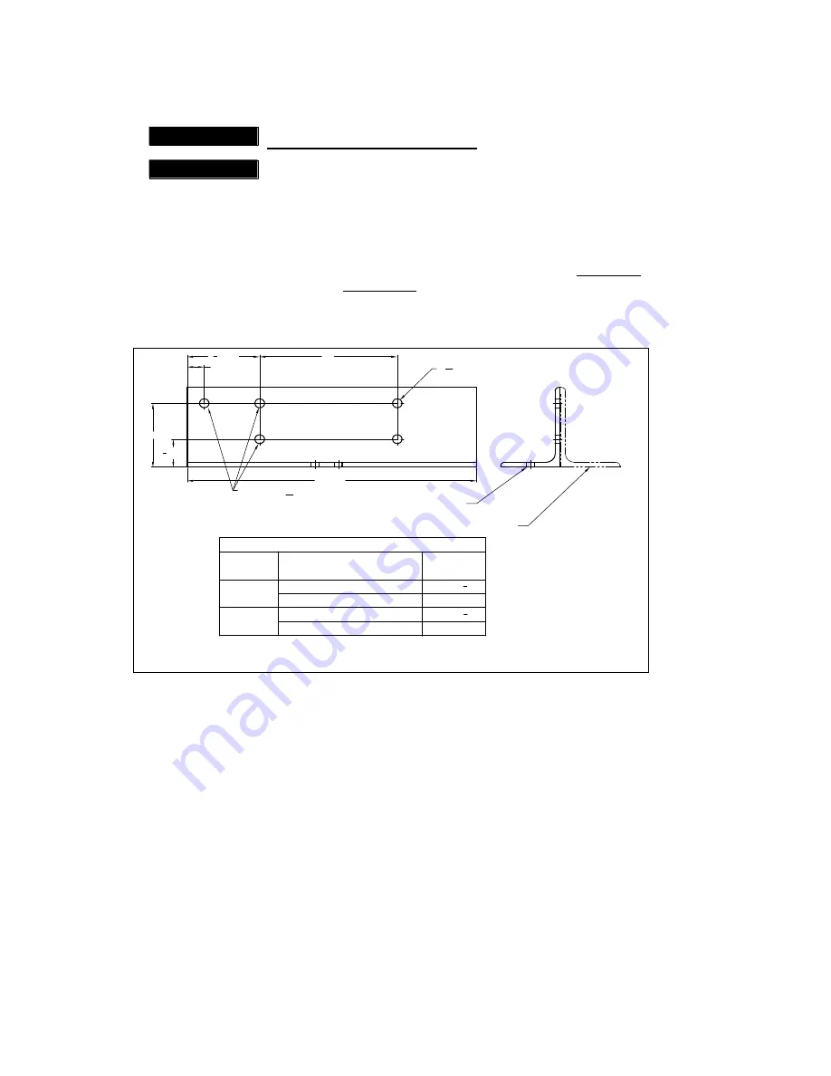
– Prior to assembling the end trucks prepare the four (4) end brackets (2 end
brackets per end truck) as follows:
Measure
“T” for the runway that the end trucks will be installed on. For Underhung “T” is the flange
width of the runway beam; for Top Running
“T” is the width of the rail head or square bar
(whichever is being used).
Drill
two 9/16” diameter holes in each of the four (4) end brackets in accordance with Figure 3-5.
4 REF.
1
3
4
REF.
1 REF.
4
1
2
REF.
17 REF.
D
EXISTING Ø
9
16
HOLES
BRACKET "A" (AS
SHOWN)
BRACKET "B" (OPPOSITE HAND)
Ø
9
16
- 2 HOLES (DRILL THESE HOLES)
FORMULA
FOR "D"
D = T + 5
D = T + 4
3
4
D = T + 5
D = T + 4
3
4
BEAM WITH FLAT FLANGE
BEAM WITH TAPERED FLANGE
RECTANGULAR SHAPED RAIL
ASCE RAIL
UNDERHUNG
TOP
RUNNING
RUNNING
SURFACE
CRANE
CONFIG.
"D" DIMENSION (INCHES)
T = I-BEAM FLANGE OR RAIL HEAD
- WIDTH MEASUREMENT
Figure 3-5 End Bracket Holes
3.3.4
Wheel Assembly Installation
– Install the Wheel Assemblies to the end trucks as shown in Figure 3-6.
Make sure you locate the Wheel Assemblies properly for your application (Underhung or Top Running)
as shown in Figure 3-7. To prevent the axle from turning when tightening the hex nut, use an air-
powered nut driver. Then, finalize the installation by applying torque to each wheel’s hex nut as follows.
75 ft-lb for HPC505
150 ft-lb for HPC510 and HPC520
Содержание HARRINGTON HPC500 Series
Страница 8: ...8 Underhung Top Running Figure 2 1 HPC500 End Truck Dimensions refer to Table 2 1...
Страница 31: ...31 NOTES...


