- 33 -
Test Chart 3
COMPONENT
ILLUSTRATION
COMPONENT
TEST PROCEDURE
TEST RESULTS
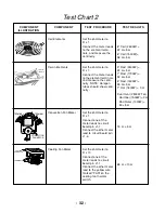
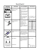
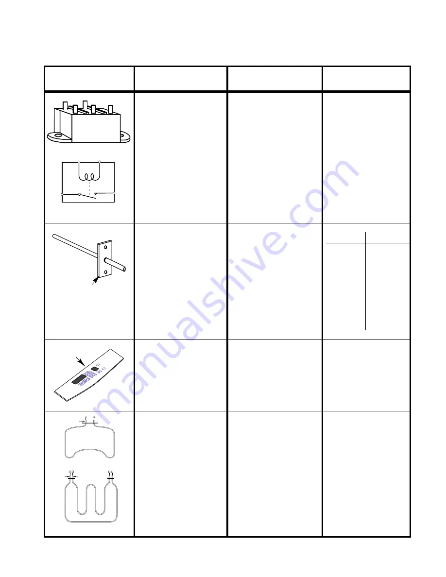
Double Line Break
(DLB) Relay
Set the ohmmeter to
R x 1.
Connect the meter leads
to DLB relay terminals
3 & 4.
Apply 120 VAC to termi-
nals 1 & 2 of the DLB
relay.
Measure the continuity
at pins 3 & 4 with and
without AC power
applied.
DOUBLE LINE
BREAK RELAY
RED
RED
WHITE
YELLOW
COM
NO
1
2
3
4
OVEN TEMPERATURE
SENSOR
Oven Temperature
Sensor
Set the ohmmeter to
R x 100.
Connect one of the
meter leads to circuit
board pin P1-10.
Connect the other meter
lead to circuit board pin
P1-11.
Temp (˚F) Resist (
Ω
)
32
±
1.9
1000
±
4.0
75
±
2.5
1091
±
5.3
250
±
4.4
1453
±
8.9
350
±
5.4
1654
±
10.8
450
±
6.9
1853
±
13.5
550
±
8.2
2047
±
15.8
650
±
8.6
2237
±
18.5
800
±
13.6 2667
±
24.4
120 VAC Not Applied =
∞
Ω
.
120 VAC Applied = 0
Ω
.
CONTROL PANEL
Capacitive Glass Touch
Panel.
Unplug the unit, wait 10-
seconds, plug the unit
back in, and run the pro-
gram sequence on page
23 of this Job Aid.
All keypads touched,
should show a response.
Set the ohmmeter to R x 1.
Connect the meter leads
to the element terminals
and measure the resis-
tance.
BAKE
ELEMENT
OUTER
ELEMENT
INNER
ELEMENT
Broil Element.
Broil:
Inner = 35
±
5
Ω
.
Outer = 55
±
5
Ω
.
Bake = 20
±
5
Ω
.
Bake Element.
Содержание KERC500B
Страница 1: ...KITCHENAID ELECTRONIC RANGE CONTROLS B D LINE WALL OVENS JOB AID Part No 4317169 ...
Страница 4: ... iv NOTES ...
Страница 47: ... 43 NOTES ...
Страница 93: ... 45 QUESTIONS ...


