background image

7-1

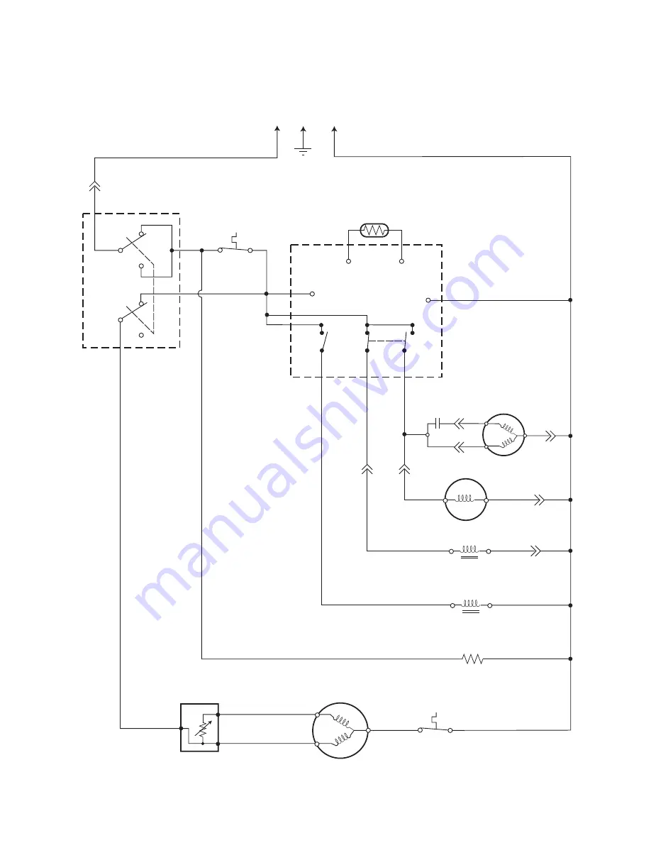
WIRING DIAGRAM & STRIP CIRCUITS

WIRING DIAGRAM

BK

BK

C1

C2

PK

RD

B1

A1

A2

RD

RD

OR

BU

LBU

LBU

BK

BK

BK

BU

BK

WH

WH

WH

WH

WH

WH

WH

BK

VT

WH

WH

OR

BR

2

3

1

5

6

4

GR

L1

N

PTC Relay

Master
Switch

M

S

C

Overload

Compressor

TH1

TH2

V

U

Evaporator Thermistor

Bin Control

Thermostat

Electronic 

Control Board

Relay

X2

N.O.

N.C.

Relay

X1

Capacitor

1.0 UF

Water Pump

Condenser Fan Motor

Hot Gas Solenoid

Water Valve Solenoid

Bin Thermostat Heater

A

M

2.4 

Ω 

@ 68

°

F

4.1K 

1.2K 

270 

M = 220 

A = 314 

52 

9.7 

Ω 

@ 68

°

F

2.5K 

Ω 

@ 70

°

F

6K 

Ω 

@ 32

°

F

Содержание KAR-13

Страница 1: ...TECHNICAL EDUCATION JOB AID 4317309 KAR 13 OUTDOOR AUTOMATIC ICE MAKER Model KUIO15NNLS ...

Страница 2: ...e maker The Wiring Diagram and Strip Circuits used in this Job Aid are typical and should be used for training purposes only Always use the Wiring Diagram supplied with the product when servicing the unit GOALS AND OBJECTIVES The goal of this Job Aid is to provide detailed information that will enable the service technician to properly diagnose malfunctions and repair the KitchenAid Outdoor Automa...

Страница 3: ...The Evaporator 4 3 Removing The Water Recirculation Pump 4 4 Removing The Evaporator Thermistor 4 8 Removing The Bin Thermostat 4 10 Removing The Hot Gas Valve And Solenoid 4 12 Removing The Master Switch Recirculation Pump Motor Capacitor And Electronic Control Board 4 14 Removing The Condenser Fan Motor 4 16 Removing The Condenser 4 18 Removing The Compressor 4 20 Removing The Door Door Gasket A...

Страница 4: ...BLESHOOTING 6 1 Timing Chart 6 1 Troubleshooting Chart 6 2 WIRING DIAGRAM STRIP CIRCUITS 7 1 Wiring Diagram 7 1 Strip Circuits 7 2 TECH TIPS 8 1 Cleaning The Ice Maker 8 1 Routine Cleaning 8 1 Cleaning The Spray Assembly 8 2 ...

Страница 5: ...sages in this Job Aid and on the appliance Always read and obey all safety messages This is the safety alert symbol This symbol alerts you to hazards that can kill or hurt you and others All safety messages will follow the safety alert symbol and either the word DANGER or WARNING These words mean DANGER WARNING All safety messages will tell you what the potential hazard is tell you how to reduce t...

Страница 6: ...ntistatic wrist strap Connect the wrist strap to the green ground connec tion point or to an unpainted metal sur face in the appliance OR Touch your finger repeatedly to a green ground connection point or to an un painted metal surface in the appliance Before removing the part from its pack age touch the antistatic bag to a green ground connection point or to an un painted metal surface in the app...

Страница 7: ...N 04 4th WEEK PRODUCT SEQUENCE NUMBER MODEL NUMBER K UI O 15 NN L S 0 INTERNATIONAL SALES IND OR MARKETING CHANNEL IF PRESENT PRODUCT GROUP K KITCHENAID PRODUCT IDENTIFICATION UI UNDERCOUNTER ICE MAKER MERCHANDISING SCHEME O OUTDOOR CAPACITY SIZE SERIES CONFIGURATION 15 15 WIDE FEATURES NN NON PUMP NON REVERSIBLE DOOR YEAR OF INTRODUCTION L 2002 COLOR CODE S STAINLESS STEEL ENGINEERING CHANGE NUME...

Страница 8: ...ing Diagram Location On Rear Of Front Panel MODEL SERIAL NUMBER LABEL AND WIRING DIAGRAM LOCATIONS The Model Serial Number label and Wiring Diagram locations are shown below Model Serial Number Label Location ...

Страница 9: ...rvest Cycle Time Water Consumption Per 24 Hrs 50 10 70 21 90 32 70 21 222 Watts 228 Watts 235 Watts 80 27 227 Watts 237 Watts 242 Watts 90 32 228 Watts 244 Watts 250 Watts 100 38 237 Watts 246 Watts 255 Watts Ambient Temp F C Water Temperature F C 50 10 70 21 90 32 70 21 44 Gal 38 Gal 33 Gal 80 27 39 Gal 31 Gal 27 Gal 90 32 38 Gal 24 Gal 20 Gal 100 38 31 Gal 23 Gal 16 Gal Ambient Temp F C Water Te...

Страница 10: ...1 6 OUTDOOR ICE MAKER WARRANTY ...

Страница 11: ...l codes and ordinances is required It is recommended that a separate circuit serving only the ice maker be provided Use a receptacle which cannot be turned off by a switch or pull chain Recommended Grounding Method For personal safety this appliance must be grounded This appliance is equipped with a power supply cord having a 3 prong grounding plug To minimize possible shock hazard the cord must b...

Страница 12: ... 113 PSIG 7 5 bar If the pressure exceeds 113 PSIG 7 5 bar use a pressure reducing valve Ice Maker Shutoff Valve Bin Drain Outlet Hose 5 8 I D 1 4 Fall Per Foot To Approved Floor Drain Drain Valve Air or CO2 For Long Term Storage The drain outlet hose is 5 8 16mm I D and internallyconnectedwitha2 3 17mm O D drain outlet The drain must be 1 4 fall per foot 2 cm fall per meter on horizontal runs for...

Страница 13: ...econtrollerthenswitchesthecontactsofthe relays which starts the pump and fan motors andde energizesthehotgasandwatervalves This completes the harvest cycle and starts thefreezecycle Theharvestandfreezecycles will continue until the bin is full of ice and the bin thermostat is satisfied No Adjustment Controls Are Sealed If Seals Are Broken Replace Control At low temperature conditions where the har...

Страница 14: ...3 2 WATER AND REFRIGERANT CIRCUIT ...

Страница 15: ... and their locations are shown below COMPONENT ACCESS Evaporator Thermistor Water Inlet Valve Bin Thermostat On Rear Panel Condenser Compressor Hot Gas Valve Behind Compressor Evaporator BOTTOM FRONT OF UNIT TOP OF UNIT Master Switch Condenser Fan Motor Electronic Control Board Water Recirculation Pump Recirculation Pump Motor Capacitor ...

Страница 16: ... cover see page 4 22 for the procedures 8 Remove the two screws from the water inlet valve 9 Disconnect the two wires from the water inlet valve solenoid terminals REASSEMBLY NOTES When you reconnect the inlet fill tube to the water inlet valve be sure to position it as shown in the photo above When you reinstall the water inlet valve and inlet fill tube in the ice maker be sure to fit thetubeinsi...

Страница 17: ... the top cover see page 4 22 for the procedure Evaporator Screw 1 of 4 9 Remove the four screws from the evapo rator 10 Remove the water inlet valve solenoid wires from the terminals and move them out of the way 11 Remove the evaporator thermistor screw andremovethethermistorfromtheevapo rator NOTE You will need to replace the thermistor and rebond it to the new evapo rator using the sealant provi...

Страница 18: ...5 Disconnect the water inlet line from the ice maker 6 Open the ice maker door 7 Remove the ice from the storage bin 8 Remove the top cover see page 4 22 for the procedure 9 Remove the ice scoop from its holder 10 Remove the hex screws from the holder and remove the holder from the unit Holder Ice Scoop 13 Push out on the left and right locking tabs and pull the water reservoir out of the unit 11 ...

Страница 19: ...nd remove the cover from the ice maker Water Recirculation Pump Cover Screw Rear Channel Cover Screw 1 0f 6 19 Remove the four evaporator screws and the four ice making housing screws Ice Making Housing Screw 1 of 4 Drain Hose Evaporator Screw 1 of 4 16 Disconnect the recirculation pump 3 wire connector 17 Cut the indicated wire tie 18 Remove the green ground wire screw Ground Screw Cut Wire Tie 3...

Страница 20: ...cemakingcomponenthousing so you can easily access the recirculation pump mounting screws Ice Making Component Housing Evaporator 22 Use a 9 32 socket or a phillips screw driver and remove the recirculation pump mounting screws 23 Disconnect the end of the water inlet fill tube from the recirculation pump and re move the pump 3 Pump Screws Rotate Housing Over Evaporator Water Recirculation Pump Wat...

Страница 21: ...ock WARNING Perform the following steps to reinstall the water recirculation pump 1 Connect the end of the water inlet fill tube to the recirculation pump 2 Mount the recirculation pump to the unit with its three 9 32 mounting screws 3 Reinstall the ice making component hous ing and evaporator in their proper loca tions and install the screws 4 Connect the recirculation pump 3 wire connector 5 Ins...

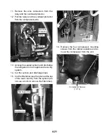
Страница 22: ...tor thermistor if the old thermistor is loose or is removed from the evaporator Make sure that you have the new thermistor available prior to removing the old one The correct sealant is provided with the new thermistor The ice maker will not operate properly if the wrong sealant is used Do not use silicone sealant it will insulate the ther mistor affecting its operation Evaporator Thermistor Brack...

Страница 23: ...rs 13 Disconnect the two evaporator thermistor wire connectors from the electronic con trol board terminals TH1 and TH2 and remove the evaporator thermistor NOTE Refer to page 4 14 for the procedure for accessing the electronic control board ...

Страница 24: ... the top cover see page 4 22 for the procedure 9 Removethesixscrewsfromtherearchan nel cover and remove the cover from the ice maker Rear Channel Cover Screw 1 0f 6 Bin Thermostat Sensing Tube Wire Connectors Wire Tie Bin Thermostat Screws Cut Black White Heater Wires 12 Dsconnect the two wires from the bin thermostat terminals 13 Cut the black and white heater wires from the harness IMPORTANT Whe...

Страница 25: ...out of the holder 15 Pull the sensing tube and heater out of the rear of the unit and remove the bin ther mostat REASSEMBLY NOTE When you reinstall the sensing tube and heater from the new bin thermostat make sure that you keep the sleeving at the same location inside the ice maker as the old sensing tube and heater Sensing Tube Holder Straighten End Of Sensing Tube Heater Sleeving ...

Страница 26: ...solenoid 2 wire con nector from the harness Cut any wire ties from around the solenoid wires Unit Compartment Cover Screw 1 0f 6 Power Cord Strain Relief Hot Gas Valve Solenoid Connector 1 Unplug ice maker or disconnect power 2 Turn off the water supply to the ice maker 3 Move the ice maker to gain access to the rear of the unit 4 Disconnect the drain outlet hose from the ice maker 5 Disconnect th...

Страница 27: ...Screw c Access the sealed system and discharge the refrigerant into an approved recovery system d Unbraze the hot gas valve from the sealed system see the photo in the left column for the joints to braze Tubing Joints REASSEMBLYNOTE Wheninstallingthenew hot gas valve use a generous amount of thermal heat trap paste between the valve and tubing joints to protect the valve when brazing Hot Gas Valve...

Страница 28: ...from the lower front panel and grille assembly and remove the assembly 4 To remove the master switch a Remove the hex nut w boot from the master switch Front Panel Grille Assembly b Disconnect the five wires from the mas ter switch terminals and remove the switch from the enclosure NOTE If necessary see the switch wiring on page 5 3 Electronic Control Board Cover Nut W Boot Cover Screw Master Swit...

Страница 29: ...vethecapacitorfrom the enclosure 6 Toremovetheelectroniccontrolboard a Disconnect the wire connectors from the electronic control board terminals b Squeezethelockingtaboneachstand off while you pull the board off the standoffs Recirculation Pump Motor Capacitor Screw Electronic Control Board Board Standoff 1 Of 4 Black White TH1 TH2 Violet A2 Black C2 Blue A1 Black C1 Pink B1 ...

Страница 30: ...Unplug ice maker or disconnect power 2 Remove the screws from the lower front panel and grille assembly and remove the assembly Condenser Fan Motor Bracket Bolts 1 of 2 4 Cut the wire tie disconnect the 2 wire condenser fan motor connector and re move the fan motor 3 Remove the two 8mm hex head bolts from the condenser fan motor bracket Wire Tie Condenser Fan Motor Wire Connector Front Panel Grill...

Страница 31: ...om the condenser fan motor and remove the motor from the bracket 6 Remove the 7 16 nut and lockwasher from the condenser fan motor shaft and remove the fan blade from the motor Condenser Fan Motor Bracket Screw 1 Of 3 7 16 Fan Blade Nut Lockwasher ...

Страница 32: ...isconnect the water inlet line from the ice maker 6 Open the ice maker door 7 Remove the ice from the storage bin 8 Remove the screws from the lower front panel and grille assembly and remove the assembly 9 Remove the two screws from the con denser flanges 10 Remove the two screws from the top con denser bracket Top Condenser Bracket Screws 11 Remove the six screws from the unit com partment cover...

Страница 33: ...4 19 12 Access the sealed system and discharge the refrigerant into an approved recovery system 13 Unbrazethetwocondenserjointsfromthe sealedsystemandremovethecondenser Joint Connections Condenser ...

Страница 34: ...the ice maker 3 Move the ice maker to gain access to the rear of the unit 4 Disconnect the drain outlet hose from the ice maker 5 Disconnect the water inlet line from the ice maker 6 Open the ice maker door 7 Remove the ice from the storage bin 8 Remove the screws from the lower front panel and grille assembly and remove the assembly Front Panel Grille Assembly 9 Remove the six screws from the uni...

Страница 35: ... an approved recovery system 14 Cut the suction and discharge lines 15 Cut the filter drier see the photo at the top of the next column from the system do not use a torch to remove the filter drier Relay Wire Overload Protector Wire 16 Remove the four compressor mounting screws from the rubber isolators and re move the compressor from the unit Compressor Screws 1 Of 4 Discharge Line Suction Line F...

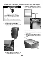
Страница 36: ...ct power 2 To remove the ice maker door a Remove the 3 8 hex head hinge pin from the bottom hinge 3 To remove the door gasket grasp the gasket and pull it out of the door channel Hinge Pin 4 To remove the top cover a Remove the two screws from the front of the cover b Lift the front of the cover unhook the rear edge from the clip and remove the cover b Pull the bottom of the door out and remove th...

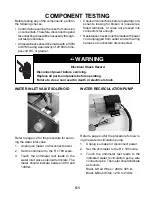
Страница 37: ...icate as follows Black Red Wires 290 to 325 Ω Black Blue Wires 210 to 230 Ω WARNING Electrical Shock Hazard Disconnect power before servicing Replace all parts and panels before operating Failure to do so can result in death or electrical shock Before testing any of the components perform the following checks Control failure can be the result of corrosion onconnectors Therefore disconnectingand re...

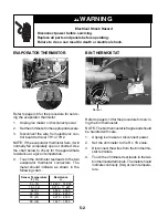
Страница 38: ...icate continuity 0 Ω at room tempera ture Refer to page 4 8 for the procedure for servic ing the evaporator thermistor 1 Unplug ice maker or disconnect power 2 Settheohmmetertotheappropriatescale 3 Disconnect the wire from electronic con trol board terminal TH1 or TH2 NOTE If the evaporator thermistor fails it will normally fail completely open or shorted Use the chart below to check for the appro...

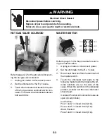
Страница 39: ...en circuit infinite Ice Position Pins 1 and 2 closed circuit 0 Ω Pins 4 and 5 closed circuit 0 Ω Wash Position Pins 2 and 3 closed circuit 0 Ω MASTER SWITCH WARNING Electrical Shock Hazard Disconnect power before servicing Replace all parts and panels before operating Failure to do so can result in death or electrical shock HOT GAS VALVE SOLENOID Refer to page 4 12 for the procedure for servic ing...

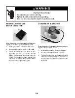
Страница 40: ...e ohmmeter test leads to the capacitor terminals The meter should deflect momentarily and then move to infinity To repeat the test reverse the ohmmeter test leads The result should be the same if the capacitor is good RECIRCULATION PUMP MOTOR CAPACITOR Refer to page 4 16 for the procedure for servic ing the condenser fan motor 1 Unplug ice maker or disconnect power 2 Set the ohmmeter to the R x 1 ...

Страница 41: ...leads to the Common C pin and the other lead to the Start S pin The meter should indicate between 8 and 11 Ω b Touch one of the ohmmeter test leads to the Common C pin and the other lead to the Run M pin The meter should indicate between 2 and 3 Ω 4 To test the overload touch the ohmme ter test leads to the terminals The meter should indicate a closed circuit 0 Ω COMPRESSOR OVERLOAD RELAY Overload...

Страница 42: ...5 6 NOTES ...

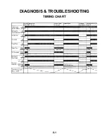
Страница 43: ...6 1 DIAGNOSIS TROUBLESHOOTING TIMING CHART ...

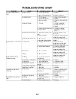
Страница 44: ...r loose connection or open and replace see page 5 5 2 Coil winding opened 2 Check for continuity between terminals and replace see page 5 5 b Overload 1 Open contacts 1 Check for continuity and replace see page 5 5 c Relay 1 Open contacts 1 Check for continuity and replace see page 5 5 3 Fan Motor or Pump Motor will not run a Wiring 1 Loose connections or broken wire 1 Repair or replace b Fan Moto...

Страница 45: ... 2 Clean system see page 8 1 2 Clean system see page 8 1 1 Clean system see page 8 1 f Water Supply Line 1 Water pressure too low and water level in Water Tank too low 1 Check for recommended pressure 9 All components run but no ice is produced 1 Water leaks 1 Check connections for water leaks and repair 2 Clogged b Nozzle 1 Clogged 2 Misaligned Nozzle and Water restriction Tank 2 Place in correct...

Страница 46: ...eck continuity see page 5 2 d Refrigerant Circuit 1 Refrigerant leak or restriction 1 Check with a leak detector Repair recharge Replace the refrigerant drier 2 Undercharged 2 Check for leaks and recharge e Fan Motor 1 See 3 f Condenser 1 Blocked 1 Clean 13 Icemaker will not stop when Bin is filled with ice a Bin Control Thermostat 1 Fused contacts 1 Replace 14 Abnormal Ice a Nozzle 1 Clogged 2 Mi...

Страница 47: ... GR L1 N PTC Relay Master Switch M S C Overload Compressor TH1 TH2 V U Evaporator Thermistor Bin Control Thermostat Electronic Control Board Relay X2 N O N C Relay X1 Capacitor 1 0 UF Water Pump Condenser Fan Motor Hot Gas Solenoid Water Valve Solenoid Bin Thermostat Heater A M 2 4 Ω 68 F 4 1K Ω 1 2K Ω 270 Ω M 220 Ω A 314 Ω 52 Ω 9 7 Ω 68 F 2 5K Ω 70 F 6K Ω 32 F ...

Страница 48: ...2 Master Switch Bin Control Thermostat Capacitor 1 0 UF Water Pump Fan Motor N BK BR OR OR RD OR BK BK BK BK LBU LBU BU BK WH WH BK WH RD L1 BK BR HARVEST MODE X1 Relay 1 2 Master Switch Bin Control Thermostat Hot Gas Solenoid Water Valve Solenoid N X2 Relay 1 2 Master Switch Bin Control Thermostat N L1 BK BR OR BK PK RD BU WH WH VT OR BK L1 BK BR ...

Страница 49: ...rs Use only LIME A WAY Cleaner see step 9 on page 8 2 Always wear rubber gloves when handling cleaning solutions ROUTINE CLEANING 1 Set the master switch to OFF and turn off the water supply to the ice maker 2 Unplugtheicemakerordisconnectpower 3 Open the ice maker door 4 Remove the ice from the storage bin 5 Remove the ice scoop and its holder 6 Push in on each of the ice guards and unhook them f...

Страница 50: ...r switch to the WASH position 12 After circulating the cleaning solution for 30 minutes position the master switch to OFF 13 Remove the reservoir and drain it then reinstall it in the unit 14 Turn on the water to the ice maker 15 Position the master switch to the WASH positionandallowthewatertocirculatefor 5 minutes 16 Position the master switch to OFF and immediately back to WASH and allow the sy...

Страница 51: ...re to remove the clog or use a suitable wire brush 7 Thoroughly rinse the spray assembly with clean water 8 Reinstall the two caps on the spray nozzle assembly 9 Reassemble the ice making components NOTE During normal operation if ice is stick ing to the evaporator plate check the weep holes in the top of the plate The holes must be open to allow ice to drop End Caps Spray Assembly Weep Hole 1 of ...

Страница 52: ...8 4 NOTES ...

Страница 53: ...8 5 NOTES ...

Страница 54: ...8 6 NOTES ...

Страница 55: ...RIZED SERVICER FOR LITERATURE ORDERS PHONE 1 800 851 4605 FOR TECHNICAL INFORMATION AND SERVICE POINTERS www servicematters com IN CANADA FOR PRODUCT SPECIFICATIONS AND WARRANTY INFORMATION CALL 1 800 461 5681 FOR TECHNICAL ASSISTANCE WHILE AT THE CUSTOMER S HOME CALL THE TECHNICAL ASSISTANCE LINE 1 800 488 4791 HAVE YOUR STORE NUMBER READY TO IDENTIFY YOU AS AN AUTHORIZED SERVICER FOR WHIRLPOOL P...

Страница 56: ......

Отзывы: