KINTECH ENGINEERING
ORBIT 360 | USER GUIDE
127
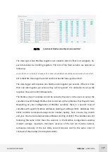
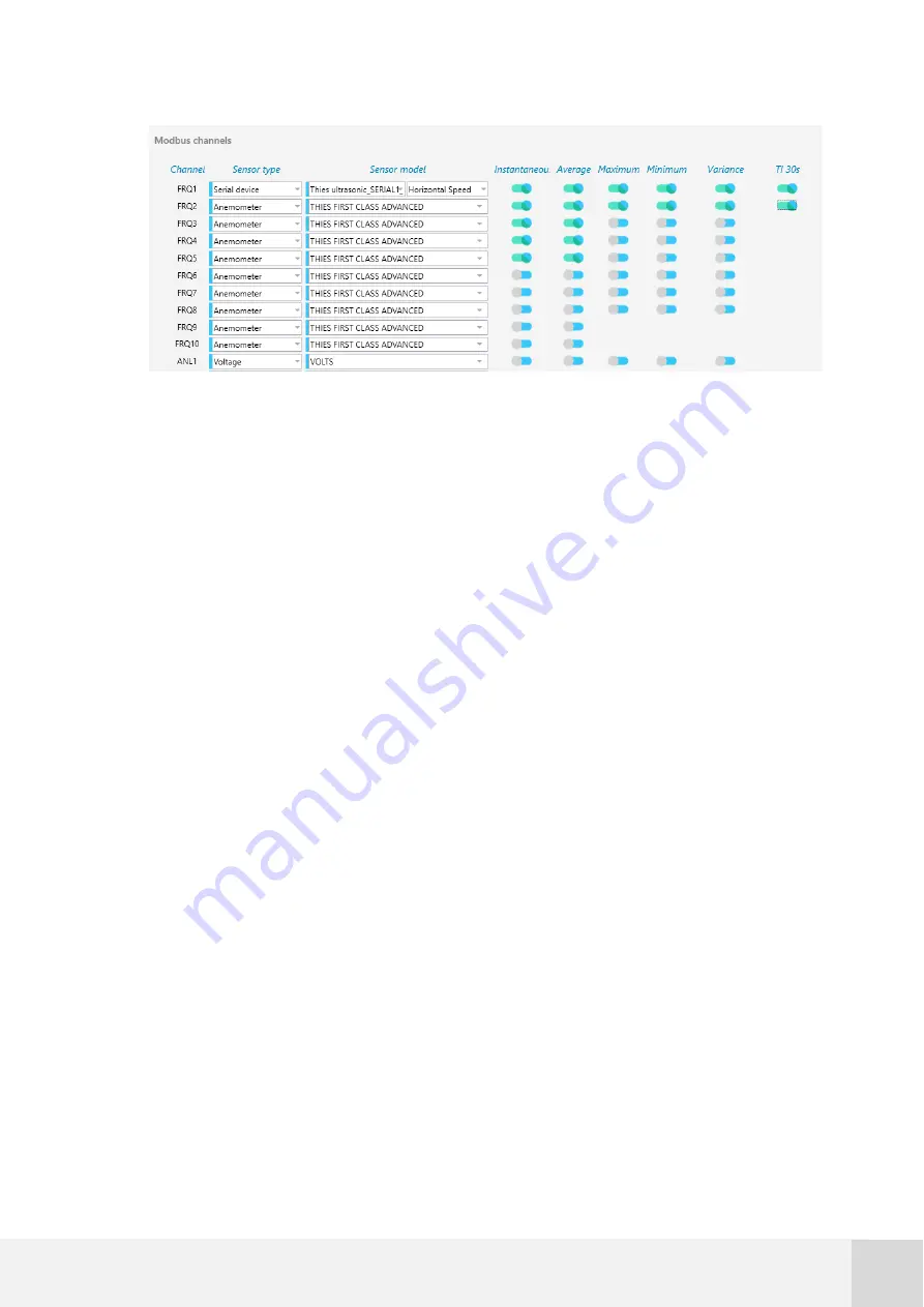
Fig. 72.
Selection of Modbus variables to be transmitted
The data type is two Modbus registers per variable coded in float (not swapped). So,
each data takes two holding registers. The bits of the float variable are ordered as
following:
b15; b14; b13; b12; b11; b10; b9; b8; b7; b6; b5; b4; b3; b2; b1; b0; b31; b30; b29; b28; b27; b26; b25; b24; b23; b22; b21; b20; b19; b18; b17; b16
b31 is
the MSB (more significant bit) and
b0
is the LSB (less significant bit).
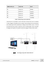
The data logger will response one Modbus interrogation per second. If there is more
than one interrogation per second, they will be ignored. It is advisable to set up the
response time out to 4000 milliseconds.
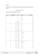
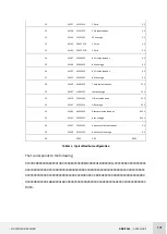
The Modbus map of variables cannot be set up by the user, so the user can set up the
variables to send through Modbus but cannot set up the addresses that they will take.
Depending on your configuration of Modbus variables, there is a specific map of
variables with specific Modbus addresses starting at address 40001. Addresses from
40001 to 40013 correspond always to site number, battery, hour, minute, day, month
and year. Channel calculations take addresses starting at 40015. The variables are sent
following the same order than the columns in the Modbus configuration window
(instant, average, maximum, minimum, variance of the last ten minutes interval,
turbulence intensity of the last thirty second interval) and for the same order of
channels of the window (from top to bottom).
Содержание ORBIT 360
Страница 1: ...LAST UPDATE 21 FEBRUARY 2020 U S E R G U I D E ORBIT 360 ...
Страница 2: ......


