Kingfisher DIMENSION AutoGet WiFi Скачать руководство пользователя страница 13

Revision 2                                                      Date: 15 Sep 2022                                                                              Page - 13 - of-20


 Click on 

instrument’s Start Analysis Button (see Fig. 2 

of section 6) to initiate pass/fail analysis.  

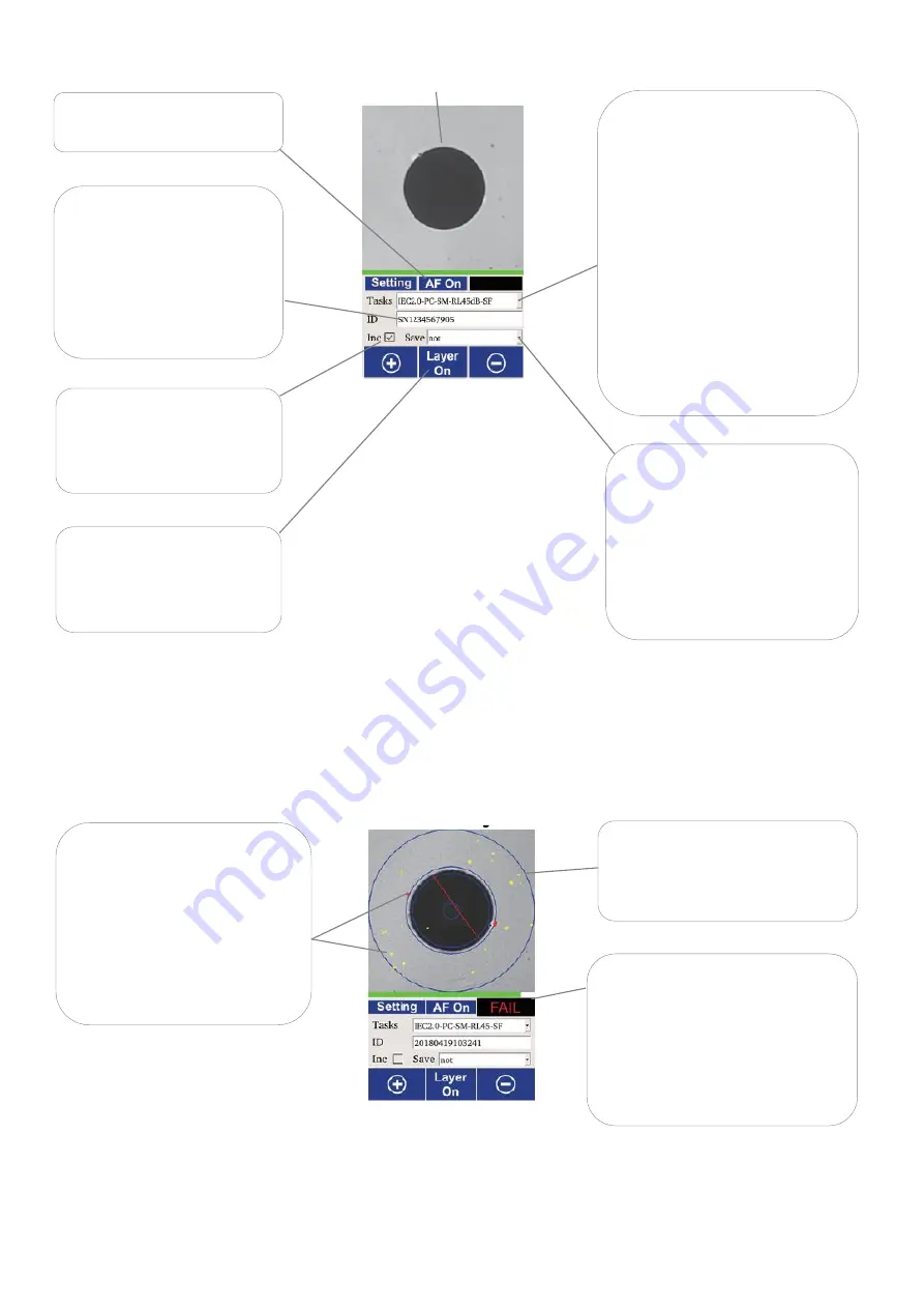
At the end of analysis, an 

Analysis Display

 will be shown as the example below.  


Click on instrument’s Start Analysis Button again to return to 

Preview Display

.  The instrument is now 

ready for the next analysis (Status Indication LED turns blue).  


Depending  on  the  connector 
type to be inspected/analyzed, 
select  the  appropriate  IEC 
specification  from  the  drop 
dropdown list.  


Note: 

IEC2.0-x

” 

specifications  are 

compliant 

with 

standard, 

IEC61300-3-35 2015 Ed2. 
 

“IEC1.0

-

x”  specifications  are 

compliant 

with 

standard, 

IEC61300-3-35 2009 Ed1. 

 
(see also section 6.1.9 for  custom 

specification) 


End-face image of connector.  


Tap to select 

“AF On” to turn 

on autofocusing.  


Tap  on  field  and  enter 
value/text  via  the  virtue 
keyboard. 
The  entered  value/text  will 
be used as the name for the 
file  in  which  the  analysis 
data/report is saved.  


If “Inc” is checked, numerical 

value in the 

ID

 field will be 

incremented upon 
completion of each analysis. 


Select a data saving option for 
the  analysis  from  dropdown 

list.    If  “not”  is  select

ed,  no 

analysis data will be saved. 


See section 7.4 for data types 
saved in instrument.  


Tap  to  select  “Layer  On”  to 

show  an  overlay  on  image 
when analysis completes.   

Blue  overlay  showing  boundaries 
of different zones on the end-face 
image . 

Yellow blobs show debris/defect 
detected  on  end-face  which 
pass the selected specification. 
 
Red 

blobs/line 

shows 

debris/scratch/defect  detected 
on  end-face  which  fail  the 
selected specification. 


Overall  analysis  result  (pass/fail)  is 
displayed here.  
In  addition,  pass  and  fail  result  is 
also  shown  by  a  green  and  red 
Status  Indication  LED  respectively 
(see  Fig.  1  of  section  6)  on 
instrument.   
 

Preview Display  

Analysis Display  

Содержание DIMENSION AutoGet WiFi

Страница 1: ...Revision 2 Date 15 Sep 2022 Page 1 of 20 AutoGet WiFi Inspection Probe User Manual Dimension by Kingfisher ...

Страница 2: ...rch 8 7 1 7 Adjusting instrument form style 8 7 1 8 Setting up instrument 8 7 1 9 Connector adaptor Installations 11 7 2 End face inspection operation 12 7 3 End face auto pass fail analysis operation 12 7 4 Download data from instrument 16 7 5 Instrument firmware update 17 8 Software operation 18 8 1 Install the software on a PC 18 8 2 Connect Instrument to PC via WiFi 18 8 3 Use software for aut...

Страница 3: ... operation from a Snap On Li ion battery rechargeable via USB C cable Good image quality with auto centering focusing Quick change adaptors for many connector styles Adjustable in 2 styles Imaging apps for Window devices via WiFi Captive dust protective cap 1 year warranty LED analysis status indicators 3 Specifications Parameters Value Optical magnification 8 72x non MPO12 5x MPO12 Field of view ...

Страница 4: ...ase 1 Carry strap 1 Operation manual 1 QA certificate 1 PC software Downloadable free from www kingfisherfiber com 5 Optional Interchangeable Inspection Adaptors Description Part number Option Mini Insp Probe Adaptor 1 25mm Male APC OPT630A Option Mini Insp Probe Adaptor 2 5mm Male APC OPT631A Option Mini Insp Probe Adaptor LC Female APC OPT632A Option Mini Insp Probe Adaptor SC Female APC OPT633A...

Страница 5: ...t Fig 1 Fig 2 Connector Adaptor On off button Torch LED Torch LED Torch LED switch Battery release latch Start analysis switch Status indication LED Release button for adjustment of the instrument s style form Touch pen Rubber flap covering SD card slot Handle ...

Страница 6: ...rotective label on instrument s slots remove cover of USB module and push the unit into instrument s slot as shown below Once installed the USB module will not be removable by user Snap On battery on instrument Auto screen brightness control sensor LCD touch screen Focus buttons Snap On Battery USB C for charging PC connection Battery status indication LEDS Push USB module into instrument slot ...

Страница 7: ...ery can be charged off the instrument while the one on instrument is being used To charge connect battery to the supplied charger or any USB power source using the supplied USB cable Different statuses of the battery is represented by the patterns of four LEDs see Fig 3 of section 6 above as tabled below LED pattern Representation Only the 1 st LED is blinking Low charge Instrument will turn off a...

Страница 8: ...see Fig 1 of section 6 above to turn and torch on or off 7 1 7 Adjusting instrument form style The instrument can be adjusted into L shape or straight forms style as shown below 7 1 8 Setting up instrument After instrument is booted up the Home Display below will be shown on LCD Tap on Setting using the supplied touch pen to show selections of various setting submenus Grip handle of instrument wit...

Страница 9: ... arrows to select the desired values If Auto is checked LCD display s brightness is adjusted automatically according to light level around the instrument If Auto is unchecked tap and move left right along the bar to adjust brightness of image Select 10 or 20 or 30 minutes from the dropdown list or never to disable auto power off Select Apply to save setting followed by OK to returned to Main Displ...

Страница 10: ...Task field Tap on Tap on Name field and enter the name of the custom standard to be created using the virtue keyboard and select Modify the relevant parameters as required under Zone Defect Scratch and select Ok Select Apply to save settings followed by Ok to exit to Main Display To delete a created custom standard Select the custom standard to be deleted from the dropdown list of Task field Tap o...

Страница 11: ...ise locknut to remove adaptor interface from instrument Align grove on instrument with pin on adaptor Turn locknut clockwise to tighten Optional MPO adaptor Adaptor interface Note It is recommended that the barrel of adaptor is cleaned using cleaning sticks before installing the adaptor onto instrument The cleaning should then be repeated frequently after the adaptor is used for inspections This i...

Страница 12: ...is auto centred focused and analysed according to one of the 16 prestored IEC IEC61300 3 35 specifications Upon completion an analysis resultant images and analysis results are stored automatically in SD card of instrument See section 7 4 for memory locations where different analysis data depend on the selected data saving mode are stored in SD card For standard connector types Install a suitable ...

Страница 13: ...n field and enter value text via the virtue keyboard The entered value text will be used as the name for the file in which the analysis data report is saved If Inc is checked numerical value in the ID field will be incremented upon completion of each analysis Select a data saving option for the analysis from dropdown list If not is selected no analysis data will be saved See section 7 4 for data t...

Страница 14: ... list Note IEC2 0 x specifications are compliant with standard IEC61300 3 35 2015 Ed2 IEC1 0 x specifications are compliant with standard IEC61300 3 35 2009 Ed1 Make sure autofocusing is on AF On Tap on field and enter value text via the virtue keyboard The entered value text will be used as the name of the file in which the analysis data report is saved If Inc is checked numerical value in the ID...

Страница 15: ...tep 2 of image acquisition Step 3 of image acquisition At this display click on instrument s Start Analysis Button see Fig 2 of section 6 Turn knob on adaptor to position 1 as shown Turn knob on adaptor to position 2 as shown At this display click on instrument s Start Analysis Button again Turn knob on adaptor to position 3 as shown At this display click on instrument s Start Analysis Button agai...

Страница 16: ...asurement failed tap Redo button to repeat 7 4 Download data from instrument Upon completion of a pass fail analysis image data report are automatically stored in the SD card in instrument The file directory can be deleted from instrument s SD card via the USB connection To download these saved image data report connect instrument to a PC using the supplied USB C cable Once connected the directori...

Страница 17: ...d on ID field Excel Data file the file is are named with value text entered on ID field Image files the file is are named with value text entered on ID field 7 5 Instrument firmware update Save a copy of the latest version of FW file in instrument s SD card At Home Display tap Setting followed by selecting About submenu Select Update and reboot instrument when prompted When rebooted at Home Displa...

Страница 18: ...dow on the PC Type in 12345678 as password when prompted 8 3 Use software for auto pass fail analysis Double click the icon on your PC s desktop to start the software Click on Connect to connect instrument to software Click on Measure or the Start Analysis Button on instrument to initiate an analysis Wait for process to complete Select a specification for analysis see section 7 3 for standard sele...

Страница 19: ...asure_Result access the analysis image data report files Copy the desired from these directories onto your PC User can create custom specification on top of the 16 prestored ones here see section 7 4 for more detail User can also select the desired directory on the PC to save analysis image data report These are default names for Data files auto generated from analysis See section 7 4 for types of...

Страница 20: ...l contact details or for return material instructions RMA Our application support or service team would be pleased to help 12 Disclaimer and Warranty This manual is given in good faith for the benefit of the user It cannot be used as the basis for claims against Kingfisher International or its representatives This product is guaranteed against defective components and workmanship for 1 years from ...

Отзывы: