ADJUSTMENTS & OPERATION
ADJUSTING OUTFEED ROLLER continued...
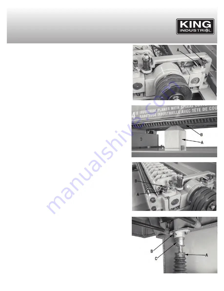
5. If the outfeed roller needs to be adjusted: Loosen the hex. nut (A) Fig.21, and
rotate the adjustment cap screw (B) using a hex. key until the outfeed roller is
just touching the top of the gauge block at one end of the table. Retighten the
hex. nut once adjustment has been made. Repeat this step at the other end of
the outfeed roller.
ADJUSTING INFEED ROLLER
The infeed roller feeds the stock into the machine as the surface is planed. The
infeed roller should be set at 0.040” below the “cutting circle”, to ensure it can feed
the stock without slipping.
To check and adjust the infeed roller:
1. Disconnect the Planer from the power source.
2. Rotate the cutterhead so that one of the cutter inserts is set at its lowest point
(you can use the drive belts to turn the cutterhead). Place the gauge block (A)
Fig.15 underneath directly underneath the cutter insert.
3. Place a 0.040” feeler gauge (B) Fig.15 on top of the gauge block, and raise the
table until the feeler gauge is touching the cutter insert set at its lowest point.
NOTE:
Don’t move the table until the adjustment has been completed. If the table
has been moved, start again at Step 1.
4. Move the gauge block (A) Fig.22 directly underneath the infeed roller (B). The
infeed roller should just touch the top of the gauge block.
5. If the infeed roller needs to be adjusted: Loosen hex. nut (A) Fig.23, and rotate the
adjustment cap screw (B) using a hex. key until the infeed roller is just
touching the top of the gauge block at one end of the table. Retighten the lock nut
once adjustment has been made. Repeat this step at the other end of the
infeed roller.
LEVELING THE TAbLE
The table is set parallel to the cutterhead from the factory, and should not need to
be adjusted. However, with time and use, it may need to be adjusted.
To check and adjust the table:
1. Rotate the cutterhead so that one of the cutter inserts is set at its lowest point (you
can use the drive belts to turn the cutterhead). Place the gauge block
directly underneath the cutter insert.
2. Raise the table until the gauge block is just touching the cutter insert.
3. Move the gauge block to the opposite side of the table. The distance between
the cutter inserts on both sides of the table should be identical.
If the table needs to be adjusted:
4. Raise the table so you are able to access the rubber boots (A) Fig.24 which
cover the table columns. Carefully clip the cable tie holding up the boot, and
lower one of the rubber boots to expose the cap screw (B) and adjustment
sleeve (C).
5. Loosen the cap screw (B), and rotate the adjustment sleeve (C) until the table is
parallel with the cutter insert set at its lowest point. Repeat this adjustment for
the other side of the table.
FIGURE 21
FIGURE 22
FIGURE 23
FIGURE 24


