

PLZ2004WB/PLZ2004WHB 9
Calibration
The booster is shipped from the factory after carrying out a strict
calibration. However, to maintain the performance, periodic
calibration is recommended.
Calibrate the master unit and the boosters as a single electronic load
in the same manner as when you calibrate the master unit alone.
For details, see "Calibration" in the PLZ1004W/PLZ1004WH User's
Manual.
For calibration, use shunt resistors and a regulated DC power supply
that match the product's current capacity.
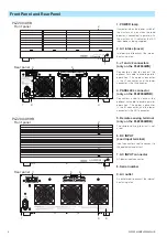
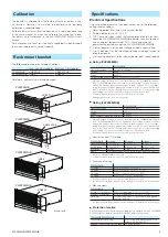
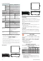
Rack mount bracket
The following brackets are available as options.
Inch-rack EIA standard
Milli rack JIS standard
PLZ2004WB
KRB3-TOS
KRB150-TOS
PLZ2004WHB KRB4
KRB200
For details, contact Kikusui distributor/agent.
465 (18.31)
479 (18.86)
57 (2.24)
132 (5.20)
37.5 (1.48)
KRB3-TOS
460 (18.1
1)
479 (18.86)
100 (3.94)
149 (5.87)
24.5 (0.965)
KRB150-TOS
KRB4
457.5 (18.01)
102 (4.02)
177 (6.97)
37.5
(1.475)
478.9 (18.85)
KRB200
457.5 (18.01)
478.9 (18.85)
199 (7.83)
50 (1.97)
50 (1.97)
50 (1.97)
24.5 (0.96)
Unit: mm (inch)
PLZ2004WB
PLZ2004WB
PLZ2004WHB
PLZ2004WHB
Specifications
Electrical Specifications
Unless specified otherwise, the specifications are for the following
settings and conditions.
•
Warm-up period: 30 minutes (with current flowing)
•
Ambient temperature: 23 ºC 5 ºC
•
TYP: These are typical values that are representative of situations
where the PLZ2004WB/PLZ2004WHB operates in an environment
with an ambient temperature of 23 ºC. These values do not
guarantee the performance of the PLZ2004WB/PLZ2004WHB.
•
% of set denotes % of the input voltage or input current setting.
•
% of f.s denotes % of the rated input voltage, rated input current or
rated input power.
•
% of reading denotes % of the input voltage or input current reading.
■
Rating (PLZ2004WB)
PLZ2004WB
Operating voltage
1.5 Vdc to 150 Vdc
1
Current
400 A
Power
2 000 W
Current setting accuracy
2
(1.2 % of set + 1.1 % of f.s)
3
1.
Minimum voltage at which the current starts flowing to the PLZ2004WB is approx.
0.3 V. The PLZ2004WB detects no signal at an input voltage less than or equal to
approx. 0.3 V and an input current less than or equal to approx. 1 % of the range
rating. If the input voltage is gradually increased from 0 V, no current will flow until
0.3 V is exceeded. Once a current greater than or equal to 1 % of the range rating
starts flowing, the current can flow at voltages less than equal to 0.3 V.
2.
Condition in which the booster is connected to the master unit.
3.
M range applies to the full scale of H range.
■
Rating (PLZ2004WHB)
PLZ2004WHB
Operating voltage
5 Vdc to 650 Vdc
1
Current
100 A
Power
2 000 W
Input resistance when the load is off 2.21 MΩ
2
1.
Minimum voltage at which the current starts flowing to the PLZ2004WHB is approx.
0.5 V. The PLZ2004WHB detects no signal at an input voltage less than or equal to
approx. 0.5 V and an input current less than or equal to approx. 1 % of the range
rating. If the input voltage is gradually increased from 0 V, no current will flow until
0.5 V is exceeded. Once a current greater than or equal to 1 % of the range rating
starts flowing, the current can flow at voltages less than equal to 0.5 V.
2.
Condition in which the booster is connected to the master unit.
•
Constant current (CC) mode
PLZ2004WHB
H range
M range
L range
Operating range
0 A to 100 A
0 A to 10 A
0 A to 1 A
Setting range
0 A to 105 A
0 A to 10.5 A
0 A to 1.05 A
Resolution
1
10 mA
1 mA
0.1 mA
Ripple
1
PLZ1004WH specification x (total power capacity/1 kW) (TYP)
1.
When one PLZ2004WHB is connected.
2.
Condition in which the booster is connected to the master unit.
•
Accuracy of setting
PLZ2004WHB
CC mode
1
(1.2 % of set + 1.1 % of f.s
2
)
CR mode
(1.2 % of set + 1.1 % of f.s
2
)
(
TYP
)
CV mode
(0.2 % of set + 0.2 % of f.s)
(
TYP
)
CP mode
(5 % of f.s
2
)
(
TYP
)
, at 23
℃
5
℃
1.
Condition in which the booster is connected to the master unit.
2.
The full scale of the range. However, for the M range, it is the full scale of the H range.
•
Measurements
PLZ2004WHB
Accuracy of voltmeter
(0.1 % of r 0.1 % of f.s)
(
TYP
)
Accuracy of ammeter
(1.2 % of r 1.1 % of f.s
1
)
(
TYP
)
Wattmeter
Displays the product of the voltmeter reading and
ammeter reading.
1.
The full scale of the range. However, for the M range, it is the full scale of the H range.
■
Protection function
Protection functions other than those listed below operate on the PLZ1004W/
PLZ1004WH. For details, see the PLZ-4W/PLZ-4WH user's manual.
PLZ2004WB/PLZ2004WHB
Overheat protection (OHP)
Turns off the load when the heat sink
temperature reaches 95 ºC
Reverse connection protection (REV) Protection by fuse