

6 PLZ2004WB/PLZ2004WHB
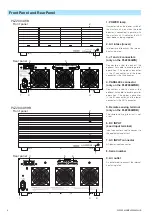
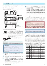
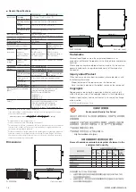
Connecting the Load Wires
Consider the current that you will be using, and use wires that are
thick as possible. Also, wire them as short as possible. Use load
wires that have the same length and cross-sectional area.
The load input terminal of the master unit (PLZ1004W/PLZ1004WH) is
not designed to handle as large a current as the load input terminal
of the booster. Separate the load wires that are connected to the EUT
into those that are connected to the master unit and those that are
connected to the boosters.
Master unit
Load input
terminals
Load input
terminals
Load input
terminals
Equipment under test
Use wires that are as thick as possible,
and wire them as short as possible.
Use load wires that have the same length
and cross-sectional area.
Booster 1
Booster 2
Example: Connection
of two boosters
WARNING
Possible electric shock.
•
Do not touch the load input terminal while the power is on.
•
Be sure to use the load input terminal cover.
CAUTION
•
To avoid damaging the product, observe the following
precautions. Be sure to use the load input terminals on the rear
panel on the master unit. Do not connect other equipment to the
load input terminal on the front panel.
•
There is a danger of overcharge. Attach crimping terminal to the
wire and use the set of screws that came with the package for
connection.
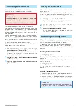
■
Connecting load wires to the PLZ2004WB
1
Check that the POWER switch of master unit is off ( ).
2
Check that the booster power cords are not
connected.
3
Make sure that the output of the EUT is off.
4
Connect load wires to the load input terminal on the
master unit's rear panel as shown in the PLZ1004W
user's manual.
5
Connect the load wires to the load input terminals on
the booster using the included load input terminal
screw set.
Bolt (M12 × 25)
Spring washer (M12)
Nut (M12)
Crimping terminal
Be sure to use the
included screw set.
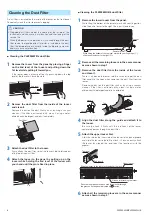
6
For each of the booster's load input terminals, wrap
the included auxiliary band around the space between
the rear panel and the bolt.
The auxiliary band prevents the load input terminal cover from
slipping. Wrap the belt tightly to fill in the space between the
panel and the bolt.
Wrap the auxiliary band around the space
between the rear panel and the bolt.
Wrap the belt tightly to fill in the space
between the panel and the bolt.
Auxiliary band
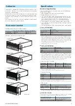
7
Wrap the load input terminal covers around the
booster's load input terminals.
Wrap the load input cover over
the auxiliary band and the load
input terminal.
Wrap the load input
terminal cover so that
there is as little space
here as possible.
Load input terminal
cover
8
Connect the load wires of the master unit and the
boosters to the EUT.
9
Check the polarity of the connections.
This completes the procedure for connecting the load wires.
■
Connecting load wires to the PLZ2004WHB
The methods for connecting load wires to a booster's load input
terminal and for using the load input terminal covers and lock plates
are the same as the methods for the PLZ1004WH. For details, see the
PLZ1004WH user's manual.
1
Check that the POWER switch of master unit is off (
).
2
Check that the booster power cords are not
connected.
3
Make sure that the output of the EUT is off.
4
Connect load wires to the load input terminal on the
master unit's rear panel as shown in the PLZ1004WH
user's manual.
5
Connect load wires to the load input terminal on the
booster as shown in the PLZ1004WH user's manual.
6
Connect the load wires of the master unit and the
boosters to the EUT.
7
Check the polarity of the connections.
This completes the procedure for connecting the load wires.