background image

Performance Test Calibration

2


U2741A USB Modular 5.5 Digits Digital Multimeter Service Guide

19

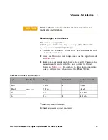
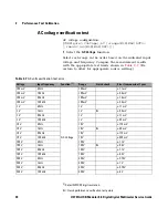
DC current gain verification test 

DC current configuration: 


(

CONFigure:CURRent[:DC] [<range|MIN|MAX|AUTO>


[,resolution|MIN|MAX|DEF>]])

1

Connect the calibrator to the front panel current HI and 
LO input connectors. 

2

Select each function and range based on the input current 
in 

Table 2- 4

3

Make a measurement and observe the result. Compare the 
measurement results with the appropriate test limits 
shown in 

Table 2- 4

. (Be certain to allow for appropriate 

source settling time when using the Fluke 5520A.) 

[1] 

Select NPLC 20 digit resolution.

Q

 = Quick performance verification test points 

C A U T I O N

Set the calibrator output to 0 V before disconnecting it from the 
multimeter input terminals

Table 2-4

DC current gain verification

 Input

 Function 

[1]

 Range

 Quick check

 Error from nominal 1 
 year

 10 mA


DC Current

 10 mA


Q

 ± 7.5 µA

 100 mA

 100 mA

 ± 65 µA

 1 A

 1 A

 ±1.57 mA

 2 A

 2 A


Q

 ±3.14 mA

Содержание U2741A

Страница 1: ...Keysight U2741A USB Modular 5 5 Digits Digital Multimeter Service Guide ...

Страница 2: ......

Страница 3: ......

Страница 4: ...Technology Licenses The hardware and or software described in this document are furnished under a license and may be used or copied only in accor dance with the terms of such license Restricted Rights Legend U S Government Restricted Rights Soft ware and technical data rights granted to the federal government include only those rights customarily provided to end user cus tomers Keysight provides t...

Страница 5: ...ect and alternating current Caution risk of electric shock Three phase alternating current Caution risk of danger refer to this manual for specific Warning or Caution information Earth ground terminal Caution hot surface Protective conductor terminal Out position of a bi stable push control Frame or chassis terminal In position of a bi stable push control Equipotentiality Category II 300 V overvol...

Страница 6: ... Turn off the device and application system power before connecting to the I O terminals When servicing the device use only the specified replacement parts Do not operate the device with the cover removed or loosened Use only the power adapter provided by the manufacturer to avoid any unexpected hazards CAUTION If the device is used in a manner not specified by the manufacturer the device protecti...

Страница 7: ...ents Operating temperature 0 C to 50 C Operating humidity 20 to 85 RH non condensing Storage temperature 20 C to 70 C Storage humidity 5 to 90 RH non condensing CAUTION The U2741A USB modular digital multimeter complies with the following safety and EMC requirements IEC 61010 1 2001 EN61010 1 2001 2nd Edition Canada CAN CSA C22 2 No 61010 1 04 USA ANSI UL 61010 1 2004 IEC 61326 2002 EN 61326 1997 ...

Страница 8: ...gnifies compliance with the Australia EMC Framework regulations under the terms of the Radio Communication Act of 1992 ICES NMB 001 indicates that this ISM device complies with the Canadian ICES 001 Cet appareil ISM est confomre a la norme NMB 001 du Canada This instrument complies with the WEEE Directive 2002 96 EC marking requirement This affixed product label indicates that you must not discard...

Страница 9: ...not discard this electrical electronic product in domestic household waste Product Category With reference to the equipment types in the WEEE directive Annex 1 this instrument is classified as a Monitoring and Control Instrument product The affixed product label is as shown below Do not dispose in domestic household waste To return this unwanted instrument contact your nearest Keysight Technologie...

Страница 10: ...VIII U2741A USB Modular 5 5 Digits Digital Multimeter Service Guide ...

Страница 11: ...echnologies calibration services 8 Calibration interval 9 Time required for calibration 9 Recommended Test Equipment 10 Self Calibration 11 Test Considerations 12 Input connections 13 Performance Verification Tests Overview 14 Performance Verification Tests 16 Zero offset verification 16 Gain verification 18 AC voltage verification test 22 AC current verification test 23 Optional AC voltage perfor...

Страница 12: ...ailable 28 Extended service contracts 28 Obtaining repair service Worldwide 28 Repackaging for Shipment 30 Cleaning 31 Electrostatic Discharge ESD Precautions 32 To Replace a Current Input Fuse 33 Troubleshooting the modular DMM 34 4 Replacement Parts 35 To Order Replaceable Parts 36 General Disassemble 37 ...

Страница 13: ... Temperature accuracy of reading no of least significant digit 6 Table 2 1 Recommended Test Equipment 10 Table 2 2 Zero offset verification test 16 Table 2 3 DC voltage gain verification 18 Table 2 4 DC current gain verification 19 Table 2 5 Ohms gain verification test 20 Table 2 6 Frequency gain verification test 21 Table 2 7 AC volts verification test error 22 Table 2 8 AC current verification t...

Страница 14: ...XII U2741A USB Modular 5 5 Digits Digital Multimeter Service Guide Contents ...

Страница 15: ...U2741A USB Modular Digital Multimeter Service Guide 1 Specifications Product Specifications 2 ...

Страница 16: ...05 0 002 0 0005 300 000 V 10 MΩ 0 018 0 005 0 0015 0 0005 Current 3 10 0000 mA 0 2 V 10 Ω 0 06 0 015 0 005 0 0025 100 000 mA 0 2 V 1 Ω 0 06 0 005 0 008 0 002 1 00000 A 0 3 V 0 1 Ω 0 15 0 007 0 005 0 002 2 00000 A 0 8 V 0 1 Ω 0 15 0 007 0 005 0 002 Resistance 4 100 000 Ω 1 0 mA 0 03 0 008 0 006 0 0008 1 00000 kΩ 1 0 mA 0 03 0 005 0 006 0 0005 10 0000 kΩ 100 μA 0 03 0 005 0 006 0 0005 100 000 kΩ 10 ...

Страница 17: ...rrent from 1 A to lower current measurement may cause an additional error of approximately 0 3 of reading due to self heating and will generally dissipate within a minute AC specifications 1 1 Specifications are based on 30 minutes warm up time and calibration temperature 18 C to 28 C In manual range the settling time is 2 6 seconds while in autorange the first measurement accuracy is 1 2 Specific...

Страница 18: ...with externally accessible 2 A 250 V fast blown fuse Table 1 3 Temperature coefficient for voltage Range Frequency Hz 20 45 45 10k 10k 30k 30k 100k Temperature coefficient 100 000 mVrms 1 00000 V 10 0000 V 100 000 V 250 000 V 0 02 0 02 0 02 0 02 0 05 0 02 0 1 0 02 Table 1 4 AC accuracy for current 1 Function Range Burden voltage Current shunt Accuracy input of reading of range Frequency Hz 20 45 4...

Страница 19: ...e wave measurement Table 1 5 Temperature coefficient for current Range Frequency Hz 20 45 45 10k 10k 30k Temperature coefficient 10 0000 mA 100 000 mA 1 00000 A 2 0000 A 0 02 0 02 0 02 0 02 0 02 0 02 Table 1 6 Frequency accuracy Functions Range Accuracy of reading of range Minimum input frequency Temperature coefficient Frequency 20 to 300 kHz 0 0200 0 003 1 Hz 0 005 Table 1 7 Frequency sensitivit...

Страница 20: ...eter Service Guide 1 Specifications Temperature specifications Table 1 8 Temperature accuracy Function Thermistor type Range Accuracy Temperature coefficient Temperature 5 kΩ thermistor 80 0 C to 150 0 C 112 F to 302 F Probe accuracy 0 2 C 0 002 C ...

Страница 21: ...t Equipment 10 Self Calibration 11 Test Considerations 12 Performance Verification Tests Overview 14 Performance Verification Tests 16 This chapter contains performance test and calibration procedures The performance tests procedures allow you to verify that the multimeter is operating within its published specifications ...

Страница 22: ...emory does not change when power has been off or after a remote interface reset Keysight technologies calibration services When your instrument is due for calibration contact your local Keysight Service Center for a low cost recalibration The U2741A is supported on automated calibration systems which allows Keysight to provide this service at competitive prices WARNING SHOCK HAZARD Only service tr...

Страница 23: ...nted beyond the one year calibration interval Keysight does not recommend extending calibration intervals beyond two years for any application Time required for calibration The U2741A can be automatically calibrated under computer control With computer control you can perform the complete calibration procedure and performance verification tests in less than 30 minutes once the instrument is warmed...

Страница 24: ...less accurate yet stable sources The output value measured from the source can be entered into the instrument as the target calibration value Table 2 1 Recommended test equipment Application Recommended equipment Recommended accuracy requirements Zero Calibration Shorting Plug Dual banana plug with copper wire short between the two terminals DC Voltage Fluke 5520A 1 5 instrument 1 year spec DC Cur...

Страница 25: ...ths or after 2000 hours of operation If the ambient temperature is higher than 10 C from the calibration temperature To maximize the measurement accuracy When you experience abnormal operation To verify proper operation after repair To start self calibration perform the following 1 Click Tools Self Calibration 2 Click Ok when the message is shown 3 Wait for a few minutes for the self calibration p...

Страница 26: ... reduce settling and noise errors Keep the input cables as short as possible Connect the input cable shields to the ground Except where noted in the procedures connect the calibrator LO source to the ground at the calibrator It is important that the LO to the ground connection be made at only one place in the circuit to avoid ground loops As the instrument is capable of making very accurate measur...

Страница 27: ... the dual banana plug with a copper wire short between two terminals for low thermal offset measurement Shielded twisted pair PTFE interconnect cables of a minimum length are recommended between the calibrator and the multimeter Cable shields should be earth ground referenced This configuration is recommended for optimal noises and settling time performance during calibration ...

Страница 28: ...hat are not performed with every calibration Perform these tests to verify additional specifications or functions of the instrument Quick performance check The quick performance check is an abbreviated performance test specified by the letter Q in the performance verification tests This test provides a simple method to achieve high confidence in the instrument s ability to functionally operate and...

Страница 29: ...rmance check adjustment or repair is required Adjustment is recommended at every calibration interval If adjustment is not made you must establish a guard band using no more than 80 of the specifications as the verification limits NOTE Make sure you have read Test Considerations on page 12 before doing the performance verification tests ...

Страница 30: ...est 1 Connect the Shorting Plug to the voltage HI and LO input terminals see Input connections on page 13 Leave the current inputs open 2 Select each function and range in the order shown in the table below Make a measurement and observe the result Compare the measurement results to the appropriate test limits shown in Table 2 2 NOTE Note that resistance measurements use the Null math function Nul...

Страница 31: ...null function is not used in KMM software Q Quick performance verification test points Short DC Volts 100 mV 8 µV Short 1 V Q 50 µV Short 10 V 0 5 mV Short 100 V 5 mV Short 300 V 15 mV Short 2 Wire Ohms and 4 Wire Ohms 100 Ω 8 mΩ 2 Short 1 kΩ 50 mΩ 2 Short 10 kΩ Q 500 mΩ 2 Short 100 kΩ 5 Ω Short 1 MΩ 50 Ω Short 10 MΩ 500 Ω Short 100 MΩ 5 kΩ Table 2 2 Zero offset verification test Input Function 1 ...

Страница 32: ...front panel HI and LO input terminals 2 Select each function and range based on the input voltage as shown in Table 2 3 3 Make a measurement and observe the result Compare the measurement results with the appropriate test limits as shown in Table 2 3 Be certain to allow for appropriate source settling when using the Fluke 5520A 1 Select NPLC 20 digit resolution Q Quick performance verification tes...

Страница 33: ...Make a measurement and observe the result Compare the measurement results with the appropriate test limits shown in Table 2 4 Be certain to allow for appropriate source settling time when using the Fluke 5520A 1 Select NPLC 20 digit resolution Q Quick performance verification test points CAUTION Set the calibrator output to 0 V before disconnecting it from the multimeter input terminals Table 2 4 ...

Страница 34: ...rement results with the appropriate test limits shown in the following table Be certain to allow for appropriate source settling 1 Select NPLC 20 digit resolution 2 The specifications are for 2 wire or 4 wire ohms using the null function in KMM software Add 0 2 Ω error if null function is not used in KMM software Q Quick performance verification test points Table 2 5 Ohms gain verification test In...

Страница 35: ...order based on the input voltage and frequency indicated in Table 2 6 Compare the measurement results with the appropriate test limits shown in the Table 2 6 Be certain to allow for appropriate source settling 1 Select NPLC 20 digit resolution Q Quick performance verification test points Table 2 6 Frequency gain verification test Voltage Input frequency Function 1 Range Quick check Error from nomi...

Страница 36: ...igit resolution Q Quick performance verification test points Table 2 7 AC volts verification test error Voltage Input frequency Function 1 Range Quick check Error from nominal 1 year 100 mV 45 Hz AC Voltage 100 mV 1 1 mV 100 mV 10 kHz 100 mV 0 3 mV 100 mV 30 kHz 100 mV 1 8 mV 100 mV 100 kHz 100 mV 5 3 mV 1 V 45 Hz 1 V 11 mV 1 V 1 kHz 1 V Q 3 0 mV 1 V 30 kHz 1 V 11 mV 1 V 100 kHz 1 V 32 mV 10 V 45 ...

Страница 37: ...st limits shown in Table 2 8 Be certain to allow for appropriate source settling 1 Select NPLC 20 digit resolution Q Quick performance verification test points CAUTION Set the calibrator output to 0 V before disconnecting it from the multimeter input terminals Table 2 8 AC current verification test Current Input frequency Function 1 Range Quick check Error from nominal 1 year 10 mA 1 kHz AC Curren...

Страница 38: ... AC Voltage function 2 Select each range in the order based on the input voltage and frequency Compare the measurement results with the appropriate test limits shown in the Table 2 9 Be certain to allow for appropriate source settling 1 Select NPLC 20 digit resolution Q Quick performance verification test points Table 2 9 Optional AC voltage performance verification test Voltage Input frequency Fu...

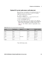
Страница 39: ...EF 1 Select the AC Current function 2 Select each range in the order based on the indicated input current and frequency Compare the measurement results with the appropriate test limits shown in the Table 2 10 Be certain to allow for appropriate source settling 1 Select NPLC 20 digit resolution Table 2 10 Optional AC current performance verification test Current Input frequency Function 1 Range Err...

Страница 40: ...26 U2741A USB Modular 5 5 Digits Digital Multimeter Service Guide 2 Performance Test Calibration ...

Страница 41: ...gital Multimeter Service Guide 3 Service Types of Service Available 28 Repackaging for Shipment 30 Cleaning 31 Electrostatic Discharge ESD Precautions 32 To Replace a Current Input Fuse 33 Troubleshooting the modular DMM 34 ...

Страница 42: ...ract and your instrument fails during the covered period Keysight Technologies will repair or replace it in accordance with the contract Obtaining repair service Worldwide To obtain service for your instrument in warranty under service contract or post warranty contact your nearest Keysight Technologies Service Center They will arrange to have your unit repaired or replaced and can provide warrant...

Страница 43: ...75 8100 Or visit Keysight worlwide Web at www keysight com find assist Or contact your Keysight Technologies Representative Before shipping your instrument ask the Keysight Technologies Service Center to provide shipping instructions including what components to ship Keysight recommends that you retain the original shipping carton for use in such shipments ...

Страница 44: ...umber and full serial number Place the unit in its original container with appropriate packaging material for shipping Secure the container with strong tape or metal bands If the original shipping container is not available place your unit in a container which will ensure at least 4 inches of compressible packaging material around all sides for the instrument Use static free packaging materials to...

Страница 45: ...Modular 5 5 Digits Digital Multimeter Service Guide 31 Cleaning Clean the outside of the instrument with a soft lint free slightly dampened cloth Do not use detergent Disassembly is not required or recommended for cleaning ...

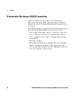
Страница 46: ...llowing guidelines will help prevent ESD damage when servicing the modular DMM or any electronic device Disassemble instruments only in a static free work area Use a conductive work area to dissipate static charge Use a conductive wrist strap to dissipate static charge accumulation Minimize handling Keep replacement parts in original static free packaging Remove all plastic styrofoam vinyl paper a...

Страница 47: ...urrent Input Fuse The current input terminal is fuse protected The fuse 2 A 250 Vac is located in the fuse folder on the front panel as shown in figure below If you determine that the fuse is faulty remove the fuse holder and replace this fuse order Keysight part number 2110 1422 Fuse Holder ...

Страница 48: ...it is inoperative Verify that the AC DC adapter is connected to the modular DMM Verify that the front panel power indicator is lit Verify that the USB cable is connected to the PC and the USB inlet in modular DMM Current input is inoperative Verify that the front panel 2 A 250 V current fuse is functional Power supply problems Check that the AC DC adapter is function and make sure that its output ...

Страница 49: ... Replaceable Parts 36 General Disassemble 37 This section provides the information of the orderable replacement parts for U2741A USB modular digital multimeter The parts available for replacement are listed in Table 4 1 with the reference part numbers and the respective part names ...

Страница 50: ...sight do the following 1 Identify the Keysight part number of the required parts as shown in the replacement parts list 2 Contact your nearest Keysight Sales Office or Service Center 3 Provide the instrument s model number and serial number Table 4 1 List of replacement parts Part number Description U2702 68301 L Bracket Assembly U2702 40004 Rubber Bumper U2702 60202 Rear Panel Assembly 2110 1422 ...

Страница 51: ... in reverse order The removable assemblies include Metal casing Rear metal casing Front metal casing which is attached to the carrier board and measurement board Front and rear rubber bumper Mechanical Disassemble Follow the instructions in this section for the instrument disassembly process Step 1 Pull the rubber bumper out to unscrew the metal casing NOTE The parts shown in the following figures...

Страница 52: ... Unscrew all the following indicated screws from the metal casing Step 3 Gently pull the front metal piece out which is attached to the carrier and measurement boards Step 4 Unscrew all the following indicated screws from the metal casing and remove the rear metal piece Screw Screw Screw Screw ...

Страница 53: ...urope tel 31 20 547 2111 Japan tel 81 426 56 7832 fax 81 426 56 7840 Korea tel 080 769 0800 fax 080 769 0900 Latin America tel 305 269 7500 Taiwan tel 0800 047 866 fax 0800 286 331 Other Asia Pacific Countries tel 65 6375 8100 fax 65 6755 0042 Or visit Keysight World Wide Web at www keysight com find assist Product specifications and descriptions in this document are subject to change without noti...

Страница 54: ...This information is subject to change without notice Keysight Technologies 2008 2014 Edition 3 November 2014 U2741 90012 U2741 90012 www keysight com ...

Отзывы: