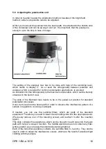
background image

17 


OPE-1-BA-e-1610 

Changing the bulb 


Halogen 


Before changing the bulb the device must be switched off and unplugged. 
To  change  the  bulb,  tip  the  device  carefully  to  the  back  or  side.  When  doing  this, 
please make sure that all microscope components are firmly fixed. The bulb holder is 
on the underside of the device. It can be opened by undoing the screws on the holder 

(see  illustration)

.  The  defective  LED  module  can  be  removed  by  loosening  the  two 

screws  fixing  the  module  and  unraveling  the  connection  point  of  its  cable.  Now  the 
new module has to be mounted in the same why as the original one. After the bulb 
holder has been replaced in the underside of the device and the screws replaced, the 
bulb replacement procedure is complete. 
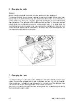


Changing the fuse 


The  fuse  housing  is  on  the  rear  of  the  microscope  below  the  mains  power  supply 
socket.  With  the  device  switched  off  and  unplugged,  you  can  pull  out  the  housing. 
When doing this, it is helpful to use a screwdriver or similar tool. The defective fuse 
can be removed from its housing and be replaced with a new one. 
After that, you just need to insert the fuse housing back into the insertion point below 
the mains power supply socket. 


Содержание OPE 118

Страница 1: ...RN Sohn GmbH Ziegelei 1 D 72336 Balingen E Mail info kern sohn com Tel 49 0 7433 9933 0 Fax 49 0 7433 9933 149 Internet www kern sohn com User instructions Polarisation microscope KERN OPE 1 OPE 118 V...

Страница 2: ......

Страница 3: ...Features 7 4 Assembly 9 4 1 Polarisation unit Microscope head 9 4 2 Objectives 9 4 3 Eyepieces 9 4 4 Colour filter 10 4 5 Condenser Polariser 10 5 Operation 10 5 1 Getting started 10 5 2 Pre focussing...

Страница 4: ...n additional risk of triggering an electric shock 1 2 Notes on the electrical system Before connecting to a mains power supply you must make sure that you are using the correct input voltage The infor...

Страница 5: ...microscope is not being used you should cover it with the enclosed dust protective cover When doing this the power supply is stopped by switching off at the main switch and unplugging the mains cable...

Страница 6: ...these are highly flammable substances You must therefore keep it away from naked flames and electrical devices which can be switched on and off and only use it in well ventilated rooms However organi...

Страница 7: ...OPE 1 BA e 1610 6 2 Nomenclature...

Страница 8: ...e pieces Objectives Illumination OPE 118 Finite Monocular WF 10x 18 mm Achromatic 4x 10x 40x 6V 20W Halogen Transmitted Product dimensions 360x200x400 mm Packaging dimensions 440x340x240 mm Net weight...

Страница 9: ...OPE 1 BA e 1610 8...

Страница 10: ...should always make sure that you do not touch the lenses with your bare fingers and that no dust enters the apertures The Bertrand lens and the analyser are inherent parts of the polarization unit The...

Страница 11: ...en you need to remove the condenser Then use the focus dial of the condenser to move the condenser holder to a low position In this way the condenser can be taken off after loosening the three screws...

Страница 12: ...soon as an image is recognisable no matter how sharp then you should only adjust the focus using the fine adjustment knob Adjusting the torque of the coarse and fine adjustment knob Next to the left a...

Страница 13: ...g on its angle position between polariser and analyser For getting ideal results the centre of the rotation axis of the table must be aligned to the centre of the optical beam path The microscopes of...

Страница 14: ...If the table is not or heavy to revolve even though the fixing screw is loosened this serves as an evidence for a significant decentration of the table 6 If the table is perfectly centre adjusted you...

Страница 15: ...objectives you should use the silver ring above the objectives see illustration When rotating the nosepiece you must always make sure that the objective which is about to be positioned in the beam pat...

Страница 16: ...ure diaphragm of the condenser to find the very best compromise between contrast and resolution for the microscopic image For the objective with the lowest magnification the lever of the aperture diap...

Страница 17: ...in the field of view The slide of the Bertrand lens needs to be in the pulled out position for standard polarisation processes It can be moved into the beam path in order to observe the interference...

Страница 18: ...connection point of its cable Now the new module has to be mounted in the same why as the original one After the bulb holder has been replaced in the underside of the device and the screws replaced t...

Страница 19: ...y centred The condenser is too low The field of view is dark or is not correctly illuminated The objective is not positioned correctly on the beam path The selector switch for the beam path is between...

Страница 20: ...Dirt dust on the front lens of the condenser Dirt dust on the object One side of the image is blurred The stage was not correctly fitted The objective is not positioned correctly on the beam path The...

Страница 21: ...materials which you can dispose of at your local recycling centre Disposal of the storage box and device must be carried out by the operator in accordance with all national or regional laws in force...

Отзывы: